60+ Years of Power Engineering  ·  ISO 9001:2015 & ISO 13485 Certified Manufacturing
0%

Hospitals depend on stable power when monitors, surgical lights, and life-support systems cannot tolerate interruption. Medical Grade Isolation Transformers help separate sensitive equipment from electrical noise, leakage currents, and certain supply faults. Their value is practical: cleaner power at the bedside, safer maintenance, and stronger continuity in critical rooms.

The World Health Organization’s Global Patient Safety Action Plan 2021–2030 identifies avoidable harm as a major healthcare challenge. Electrical reliability forms part of that wider safety picture. The International Electrotechnical Commission’s IEC 60601-1 standard sets essential safety and performance requirements for medical electrical equipment. NFPA 99 also addresses essential electrical systems, grounding, and patient-care locations in healthcare facilities. These references do not make every transformer suitable. That distinction matters.

This 2026 guide examines transformer construction, isolation performance, shielding, temperature rise, acoustic output, monitoring, and installation conditions. It also considers documentation, testing, and service support. A transformer can look impressive on a specification sheet. It may still fail a real clinical need. For example, a noisy unit beside an intensive-care bed can disturb staff and patients, while poor load assessment can create overheating during peak use. Market research from Grand View Research and MarketsandMarkets continues to show expanding healthcare infrastructure and medical-device demand, increasing attention on dependable power protection. However, market growth is not proof of product quality. Buyers should verify test reports, certification scope, fault protection, and compatibility with local healthcare codes. This guide offers a careful starting point, not a substitute for a qualified electrical engineer’s review.
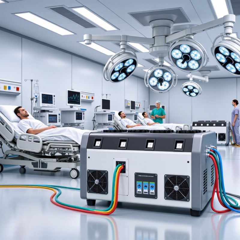
2026 Top Medical Grade Isolation Transformers Guide

Medical-Grade Isolation Transformers: Definition and Purpose

2026 Top Medical Grade Isolation Transformers Guide

Medical-Grade Isolation Transformers: Definition and Purpose

A medical-grade isolation transformer separates a clinical power circuit from the utility supply. It transfers energy through magnetic coupling, not a direct electrical connection. This separation helps limit leakage current and reduce shock risks near patients. It also supports stable power for monitors, surgical equipment, and diagnostic systems. The distinction matters.

These transformers commonly serve Group 2 medical locations, where equipment may contact the heart or critical tissue. A typical unit includes reinforced insulation, electrostatic shielding, temperature protection, and an insulation-monitoring alarm. The alarm can warn staff when insulation resistance falls below a safe threshold. In practice, the alarm panel should remain visible and audible near the patient-care area. A quiet alarm is a serious design failure.

Proper sizing requires more than adding equipment nameplates. Engineers should evaluate inrush current, continuous load, harmonic content, heat, and future expansion. A transformer that feels adequate today may become overloaded after one new imaging device arrives. Short-circuit protection and protective bonding also need coordinated verification. Installation should follow applicable medical electrical standards and local inspection requirements.

Isolation does not remove every hazard. It cannot correct poor grounding, damaged cords, or careless maintenance. Commissioning tests should document insulation resistance, leakage current, alarm operation, polarity, and temperature performance. Records help technicians identify gradual deterioration. Some designs still leave room for improvement, especially when staff receive little alarm training. Clear procedures and repeated testing remain essential in real clinical environments.

How Medical-Grade Isolation Transformers Work

2026 Top Medical Grade Isolation Transformers Guide

How Medical-Grade Isolation Transformers Work

A medical-grade isolation transformer separates the incoming power circuit from the patient-area circuit. It uses two windings around a magnetic core, rather than a direct electrical connection. Alternating current energizes the primary winding, creating a magnetic field. That field induces voltage in the secondary winding.

This separation limits unwanted current paths. If insulation fails in connected equipment, the isolated circuit can reduce the chance of current flowing through a patient to ground. Many medical units also include an electrostatic shield, low-leakage design, and insulation monitoring. These features help detect deterioration before it becomes an emergency.

Voltage may remain similar, but the electrical reference changes. That distinction is easy to miss. An isolation transformer does not automatically regulate voltage, remove every fault, or replace protective grounding. A medical room still needs coordinated wiring, overcurrent protection, testing, and documented maintenance. Real installations are less tidy than diagrams suggest.

In practice, technicians check leakage current, insulation resistance, alarm operation, temperature, and load behavior. They should test the system under realistic conditions, including equipment with switching power supplies. A transformer can perform well on paper and still fail through poor connections or neglected inspections. Qualified professionals must select and install it according to the facility’s risk assessment and applicable medical electrical standards.

Essential Safety Standards and Performance Requirements

2026 Top Medical Grade Isolation Transformers Guide

Medical isolation transformers support safer power distribution in patient-care areas. Their main role is not simply voltage conversion. They reduce shock risk by separating downstream circuits from the supply system. A compliant design should align with current medical electrical standards, including IEC 60601-1 and relevant transformer requirements such as IEC 61558-2-15. Always verify the latest edition and local installation rules.

Performance begins with controlled leakage current. Excessive leakage can reach a patient through monitoring leads, bed frames, or other conductive paths. Engineers should review insulation resistance, dielectric strength, creepage distance, and clearance. Thermal performance matters too. A transformer operating beside a warm equipment rack may exceed its rated temperature. Capacity should cover continuous loads, startup currents, and realistic future expansion without encouraging unsafe overloading.

Details decide reliability.

During commissioning, technicians should measure output voltage, leakage current, insulation resistance, temperature rise, and protective bonding. Audible noise and vibration also deserve attention in quiet clinical rooms. Shielding and grounding arrangements must be checked as a complete system, not as isolated features. One common mistake is selecting a transformer only by kilovolt-ampere rating. That approach ignores harmonics, nonlinear loads, and emergency operating conditions. Another weakness is assuming certification replaces site testing. It does not. Requirements can differ between operating rooms, intensive care spaces, and diagnostic areas, so a qualified professional should document every assumption and revisit it when equipment changes.

How to Choose the Right Medical-Grade Isolation Transformer

Choosing a medical-grade isolation transformer begins with the clinical environment, not its advertised VA rating. List every connected device, including monitors, surgical lights, imaging accessories, and mobile equipment. Ask whether these loads operate continuously or start together. A small operating room can create unexpected demand during equipment startup. Measure the real load. Then add practical headroom for future devices and temporary surges. Oversizing may increase cost, heat, and installation space without improving safety.

Confirm compliance with the applicable edition of IEC 60601-1 and local electrical requirements. Check output voltage, frequency, regulation, insulation class, temperature rise, and short-circuit protection. An electrostatic shield can reduce unwanted capacitive noise between windings. Insulation monitoring helps detect deteriorating isolation before it becomes a serious hazard. Alarm functions should be visible and audible where clinical staff can respond quickly. Do not treat certification labels as a complete evaluation. Installation quality matters too.

During selection, review the transformer’s leakage current under normal and fault conditions. Ask for tested performance data, not only marketing claims. Verify enclosure size, ventilation clearance, noise level, and maintenance access before ordering. Field experience often shows that poor ventilation shortens service life. Yet this point is easy to overlook. A perfect choice is rarely possible. The right model balances electrical safety, reliability, clinical workflow, expansion plans, and the capabilities of the facility’s qualified electrical professionals. Document the final calculations and inspection results for future service decisions.

2026 Top Medical-Grade Isolation Transformers Guide

How to Choose the Right Medical-Grade Isolation Transformer

Patient leakage current limits become more stringent as the applied-part classification moves from Type B to Type CF. When selecting an isolation transformer, verify the transformer’s insulation system, leakage-current performance, protective earth arrangement, load capacity, and compatibility with the complete medical electrical system. The values shown are commonly referenced IEC 60601-1 limits under specified test conditions; the applicable edition and local regulations should always be confirmed.

Installation, Testing, and Maintenance Procedures

Medical Grade Isolation Transformers: Installation, Testing, and Maintenance Procedures

Installation begins with a documented site assessment. Confirm the transformer rating, connected load, ventilation, and available fault protection. Qualified electrical professionals should follow local codes and the equipment’s technical instructions. Keep the enclosure accessible for inspection, but away from moisture, heat, and impact. Secure every connection, label each circuit, and verify protective bonding before energizing the system. Small details matter.

Testing should occur before clinical use and after major electrical changes. Inspect terminals, insulation, cable routing, and enclosure damage. Measure insulation resistance only with approved methods and disconnected sensitive equipment. Verify output voltage under normal load conditions. Test the insulation monitoring alarm by using the manufacturer’s approved simulation procedure. Check audible and visual indicators at the patient-care location. Record instrument settings, readings, dates, and responsible personnel. A quiet alarm is not proof of safety. The test may be incomplete.

Maintenance requires scheduled visual inspections, thermal checks, cleaning, and connection tightening when permitted. Look for unusual noise, vibration, discoloration, or rising temperature. Review alarm history and load trends instead of relying on one successful inspection. De-energize equipment before internal servicing, and confirm absence of voltage with a suitable tester. Replace damaged components through controlled procedures. Keep complete records for audits and future troubleshooting. In practice, rushed documentation is a recurring weakness. A missed reading can delay a critical decision. Recheck uncertain results.

2026 Top Medical Grade Isolation Transformers Guide - Installation, Testing, and Maintenance Procedures
Stage Data Dimension Recommended Procedure Typical Requirement or Acceptance Point Recommended Timing
Pre-Installation Application and risk assessment Confirm the transformer is intended for a medical location and identify the connected load, patient environment, essential electrical circuits, and required isolation arrangement. The selected equipment must match the medical electrical system design, local electrical code, and applicable requirements such as IEC 60364-7-710, IEC 60601-1, or the applicable national equivalent. Before procurement and installation
Pre-Installation Electrical rating verification Compare the nameplate input voltage, output voltage, frequency, apparent-power rating, short-circuit impedance, and protection class with the design schedule. Primary and secondary voltage must match the supply design. The VA or kVA rating must cover the calculated continuous load and permitted transient demand without exceeding the design temperature rise. Before energization
Pre-Installation Location and environmental conditions Install in a clean, dry, accessible area with adequate ventilation. Keep the enclosure away from water sources, corrosive chemicals, excessive dust, and avoidable vibration. Ambient temperature, humidity, altitude, ingress protection, and clearance must remain within the equipment documentation and local code limits. Do not block cooling openings. During site planning and final inspection
Installation Mechanical mounting Mount the transformer on a stable, level surface or approved support. Use suitable fasteners and maintain manufacturer-specified service clearance around the enclosure. The unit must be secure, level, free from transport damage, and positioned so that inspection, isolation, and cable termination can be performed safely. Once, at installation
Installation Protective earthing and bonding Connect the protective earth conductor to the designated earth terminal. Bond exposed conductive parts in accordance with the medical electrical installation design. The protective conductor must be correctly sized, mechanically secure, clearly identified, and continuous back to the approved earthing system. Never use the neutral conductor as a substitute for protective earth. Installation and every major alteration
Installation Cable routing and termination Route primary, secondary, protective-earth, and control wiring according to the approved drawings. Use strain relief and torque terminals to the documented value. No loose strands, damaged insulation, unsupported cable weight, excessive bend radius, or mixed circuits that could compromise separation or electromagnetic compatibility. During installation and re-termination
Installation Overcurrent and fault protection Install primary and secondary protective devices selected for the transformer rating, inrush current, conductor ampacity, and prospective fault current. Protective-device ratings and interrupting capacity must comply with the approved coordination study and applicable electrical code. Protection must not be bypassed during normal operation. At commissioning and after circuit changes
Commissioning Visual and wiring inspection Verify labels, circuit identification, enclosure condition, ventilation, terminal tightness, earthing, cable segregation, and correct fuse or breaker installation. All connections must correspond to the latest approved schematic. There must be no visible damage, contamination, loose hardware, or unapproved modification. Before first energization
Commissioning Insulation resistance test With the equipment isolated and sensitive electronics disconnected as required, test primary-to-secondary, primary-to-earth, and secondary-to-earth insulation using a calibrated insulation tester. Use the test voltage and minimum resistance specified by the applicable standard or equipment documentation. A commonly used site benchmark is at least 100 MΩ for a dry, isolated transformer, but the approved project criterion takes precedence. Initial commissioning and after major repair
Commissioning Protective-earth continuity Measure continuity from the protective-earth terminal to all accessible conductive parts using a low-resistance tester. Measured resistance must comply with the applicable medical electrical installation standard and project specification. Investigate any unstable, unusually high, or open-circuit reading. Initial commissioning and periodic safety testing
Commissioning Dielectric withstand test Perform a dielectric strength test between electrically isolated circuits only when required by the applicable standard or service procedure. Remove or isolate components that could be damaged. The test voltage, duration, leakage limit, and ramp rate must be taken from the equipment documentation or applicable standard. No flashover, breakdown, or unacceptable leakage is permitted. Factory acceptance, commissioning when specified, and major repair
Commissioning Output voltage and polarity Energize under controlled conditions and measure primary voltage, secondary voltage, phase relationship, polarity, and frequency with calibrated instruments. Readings must remain within the design tolerance under no-load and representative load conditions. Incorrect polarity or unexpected voltage requires immediate isolation and investigation. Before connection of clinical loads
Commissioning Load and temperature test Apply a representative design load while monitoring secondary voltage, input current, enclosure temperature, audible noise, and signs of overheating. Current must not exceed the rated value. Temperature rise, noise, and voltage regulation must remain within the documented limits. Stop the test if smoke, odor, vibration, or abnormal noise occurs. Initial commissioning and after load expansion
Operation Routine visual inspection Check enclosure condition, ventilation openings, warning labels, cable glands, indicator lamps, unusual noise, odor, vibration, and signs of overheating. The enclosure must remain closed and undamaged. Cooling paths must be unobstructed, and no discoloration, arcing mark, moisture, or burnt odor should be present. Monthly or according to facility risk assessment
Maintenance Cleaning and ventilation service De-energize and lock out the equipment before removing dust from external surfaces and ventilation openings with approved, non-conductive methods. Do not spray liquid into the enclosure or use compressed air in a way that drives dust into windings, bearings, terminals, or control components. Every 6 to 12 months, or more often in dusty areas
Maintenance Connection and termination inspection During an outage, inspect terminal blocks, lugs, earth connections, cable insulation, and signs of thermal stress. Retighten only to the documented torque. Connections must be tight, corrosion-free, and free of overheating marks. Any damaged cable, terminal, or insulation barrier must be repaired before return to service. Annually or during scheduled shutdown
Maintenance Thermal scanning Use a calibrated infrared camera to inspect terminals, protective devices, cable joints, and enclosure surfaces while the transformer carries a representative load. Investigate abnormal temperature differences between comparable connections. Thermal results must be interpreted according to load, ambient temperature, and the equipment manufacturer’s limits. Annually and after repeated overload events
Periodic Testing Electrical safety reassessment Repeat protective-earth continuity, insulation resistance, polarity, output-voltage, and functional checks using calibrated test equipment and a documented lockout procedure. All results must meet the current facility policy, applicable national code, and project acceptance criteria. Compare results with previous records to identify deterioration. Typically annually or based on medical-facility risk assessment
Periodic Testing Protection and alarm verification Test associated circuit breakers, fuses, monitoring devices, alarms, indicators, and remote contacts where fitted. Confirm correct operation under safe simulated conditions. Devices must operate at their intended settings, reset correctly, and provide the required local or remote indication without nuisance operation. At the interval specified by the facility maintenance program
Documentation Test record and traceability Record equipment identification, location, ratings, test instruments, calibration status, test conditions, measured values, defects, corrective actions, and the responsible technician. Records must be legible, dated, retained according to the healthcare facility policy, and available for electrical-safety audits and future trend comparison. Every inspection, test, repair, and modification
Safety Lockout and return-to-service control Before maintenance, isolate all sources, apply lockout/tagout, verify absence of voltage, discharge stored energy, and control access. Before energizing, remove tools, reinstall covers, and notify affected personnel. Only authorized and competent personnel may perform the work. The transformer must not be returned to clinical service until inspection results are acceptable and the work permit is closed. Every maintenance or repair activity

FAQS

What is a medical-grade isolation transformer?

It separates a clinical power circuit from the utility supply through magnetic coupling. No direct electrical connection exists. This separation can reduce leakage current and shock risks.

Where are medical isolation transformers commonly used?

They commonly serve Group 2 medical locations. These areas may involve equipment contacting the heart or critical tissue. Patient-care rooms need careful power design.

What safety features should a suitable transformer include?

Important features include reinforced insulation, electrostatic shielding, temperature protection, and insulation monitoring. An alarm should warn staff when insulation resistance decreases.

Where should the insulation-monitoring alarm be installed?

The alarm panel should remain visible and audible near the patient-care area. Staff must notice it quickly. A quiet alarm is a serious design failure.

How should engineers size the transformer?

Engineers should assess continuous load, inrush current, harmonics, heat, and future expansion. Nameplate totals alone are not enough. One new imaging device may overload an undersized unit.

Does a higher kilovolt-ampere rating guarantee safe performance?

No. The rating may ignore nonlinear loads, harmonics, startup currents, and emergency conditions. Capacity should support real operating demands without unsafe overloading.

What tests should be completed during commissioning?

Technicians should document output voltage, leakage current, insulation resistance, temperature rise, and protective bonding. They should also check alarm operation, polarity, noise, and vibration.

Can an isolation transformer remove every electrical hazard?

No. It cannot fix poor grounding, damaged cords, or careless maintenance. Site testing remains necessary, even when equipment has certification. This point deserves repeated review.

Why does staff training matter after installation?

Staff should understand alarm meanings and response procedures. Repeated testing helps identify gradual deterioration. Training may be overlooked, and that weakness can reduce real-world safety.

Conclusion

Medical Grade Isolation Transformers are specialized electrical safety devices designed to provide reliable power separation in healthcare environments. By isolating connected equipment from the main electrical supply, they help reduce leakage currents, limit electrical noise, and improve protection for patients, medical staff, and sensitive devices. This guide explains their operating principles, including magnetic energy transfer between windings and the role of shielding, grounding, and monitoring systems in maintaining safe performance.

It also reviews essential safety standards, insulation requirements, temperature limits, overload protection, and leakage-current control. Readers will learn how to select the appropriate transformer by considering power capacity, voltage, load type, installation location, and future expansion needs. Finally, the guide outlines practical procedures for installation, commissioning, routine testing, cleaning, inspection, and preventive maintenance, helping facilities support dependable operation and extend equipment service life.


Evelyn

Evelyn

Evelyn is a dedicated marketing professional with a deep understanding of the company’s products, customers, and market dynamics. Through thoughtful research and clear communication, she transforms complex product information into practical insights that help readers make confident decisions. As a......