China Top 10 Programmable High Voltage Electronic Loads introduces the manufacturers shaping modern high-voltage testing in China. These systems help engineers validate power supplies, batteries, inverters, photovoltaic equipment, and electric vehicle components. A reliable load must do more than absorb energy. It must reproduce demanding conditions with accuracy, stability, and controlled risk.
Power electronics expert Dr. Robert W. Erickson defined the field clearly: “Power electronics is the technology associated with efficient conversion, control, and conditioning of electric power.” That principle guides this selection. Each company should be examined through practical indicators, including voltage range, current capacity, power rating, dynamic response, and operating modes. Constant-current, constant-voltage, constant-resistance, and constant-power functions deserve close attention. Protection against overvoltage, overheating, reverse polarity, and abnormal current is equally important.
On a laboratory bench, specifications become physical details. A cooling fan may run continuously beside a warm test rack. A slow transient response can distort a battery discharge curve. Poor remote sensing may create a voltage error several meters away. Software quality also matters. Engineers need stable communication, clear data records, and repeatable test sequences.
No ranking is perfect. Some manufacturers publish limited technical data. Others offer strong hardware but weaker documentation or support. That uncertainty deserves honest attention. This guide compares the China Top 10 Programmable High Voltage Electronic Loads using available technical evidence, application experience, and purchasing considerations. The goal is not to promote a single brand. It is to help engineers choose a safer, more precise, and more practical solution for demanding high-voltage tests.
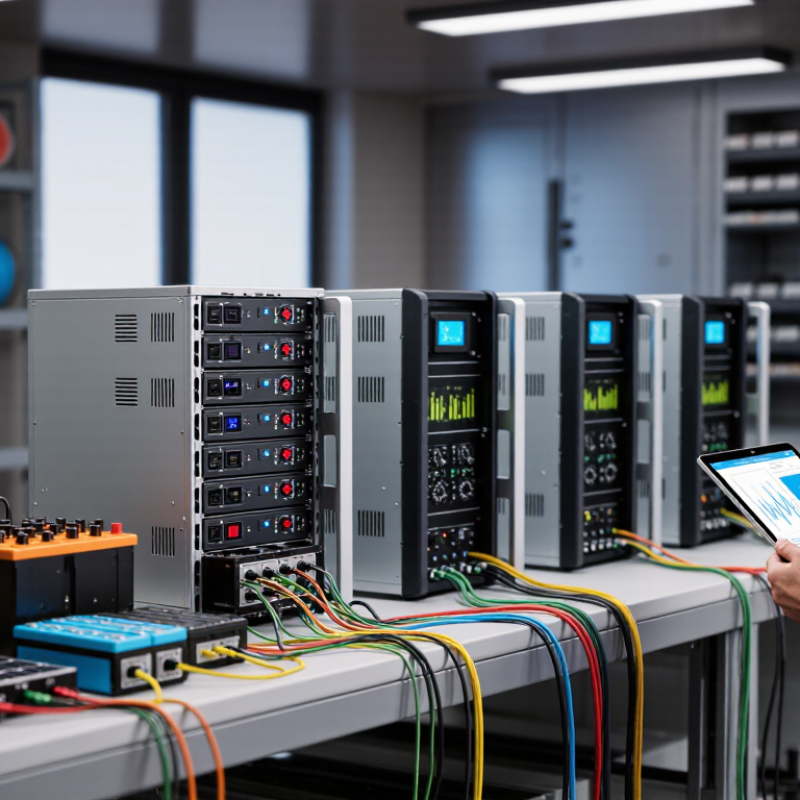
A programmable high-voltage electronic load is a controlled test instrument that absorbs electrical energy from a source. It helps engineers evaluate power supplies, batteries, converters, and charging equipment under repeatable conditions. Unlike a passive resistor, it can imitate changing real-world demands. The word programmable matters. Operators set voltage, current, power, or resistance through a panel or computer interface. Safety depends on more than the voltage rating. Insulation distance, grounding, cooling, and emergency shutdown controls also require careful verification.
Core functions include constant-current, constant-voltage, constant-resistance, and constant-power modes. Constant-current mode draws a fixed current, even when source voltage changes. Constant-power mode is useful for testing systems facing variable battery voltage. Dynamic loading can switch between light and heavy demand within milliseconds. These transitions reveal control-loop instability, voltage sag, and excessive ripple. Accurate instruments measure voltage, current, power, capacity, and response time. Some support remote commands and automatic test sequences, reducing manual recording errors.
In practical testing, I connect the load with short, properly rated cables and check polarity before energizing. I begin at low power, then increase demand gradually while watching temperature and waveform changes. A thermal camera can reveal hot terminals that ordinary readings miss. Yet no setup is perfect. Lead inductance, airflow, and sensor tolerance can distort results. I have seen a stable reading hide a loose connection. That result needs investigation, not immediate approval. Repeating the test at different power levels improves confidence and exposes weaknesses.
This chart shows the electrical power dissipated by a programmable electronic load operating at a constant 10 A current across representative DC bus voltage levels. The values are calculated using P = V × I and illustrate the core constant-current loading function used for power-supply, battery, inverter, photovoltaic, and electric-vehicle component testing. It is not a ranking of manufacturers or brands.
China Top 10 Programmable High Voltage Electronic Loads
Key Technologies and Operating Principles of High-Voltage Electronic Loads
Programmable high-voltage electronic loads convert electrical energy into controlled heat. Their core circuit usually uses power MOSFETs or IGBTs, a precision sensing resistor, and a feedback controller. The controller compares measured voltage or current with the programmed value. It then adjusts device conduction within microseconds. Common operating modes include constant current, constant resistance, constant power, and constant voltage. These modes help engineers test power supplies, batteries, capacitors, and converters under repeatable conditions.
Thermal management is equally important. A load may dissipate several kilowatts, so heat sinks, forced-air cooling, temperature sensors, and protective shutdown circuits work together. Accurate voltage and current sampling also affects test credibility. Isolation, overvoltage protection, overcurrent protection, and emergency stops reduce operational risk. During transient testing, the control loop must respond quickly without creating unstable oscillations. This balance is easy to underestimate. A stable reading does not always mean a stable system.
Tips: Confirm the voltage rating before connecting any source. Use short, correctly rated cables. Start with a low current setting, then increase it gradually. Watch temperature, ripple, and unusual noise during long tests. Keep a written test record. I still recheck wiring before every high-energy test, because one overlooked connection can distort results or damage equipment. Some specifications appear clear, yet real performance may change with ambient temperature and cooling airflow.
| Rank | Programmable Load Configuration | Typical DC Voltage Range | Typical Power Class | Typical Current Range | Main Control Modes | Key Technology and Operating Principle | Typical Applications |
|---|---|---|---|---|---|---|---|
| 1 | High-Power Modular DC Load | 0–1,000 VDC | 30–100 kW | Up to 300 A | CC, CP, CR, CV, dynamic sequence | Parallel power modules use controlled MOSFET or IGBT dissipation stages. A digital controller regulates the conduction angle or device current to maintain the programmed load profile. | Battery packs, DC bus systems, energy-storage converters, and power supplies |
| 2 | 800 V-Class Automotive DC Load | 0–800 VDC | 6–30 kW | Up to 150 A | CC, CP, CR, pulse, transient | A feedback loop compares measured voltage and current with the setpoint, then adjusts semiconductor conduction to reproduce charging, acceleration, regenerative, or fault-load conditions. | Electric-vehicle batteries, onboard chargers, DC fast-charging equipment, and traction inverters |
| 3 | 1,200 VDC Wide-Range Load | 0–1,200 VDC | 10–60 kW | Up to 200 A | CC, CP, CR, CV, list mode | Series-connected power devices and isolated measurement circuits provide higher voltage withstand capability. Active balancing and protection limit device stress during high-voltage transients. | Industrial inverters, photovoltaic converters, high-voltage battery systems, and aviation power units |
| 4 | 1,500 VDC Renewable-Energy Load | 0–1,500 VDC | 20–100 kW | Up to 150 A | CC, CP, CR, MPPT emulation, dynamic profile | High-voltage switching cells operate in a controlled linear or pulse-width-modulated region. The controller can emulate constant-current, constant-power, or photovoltaic operating characteristics. | Utility-scale photovoltaic inverters, DC combiner systems, and renewable-energy storage converters |
| 5 | Regenerative High-Voltage Load | 0–1,000 VDC | 10–80 kW | Up to 250 A | CC, CP, battery simulation, energy recovery | Instead of converting all absorbed energy into heat, a bidirectional converter transfers part of the DC input energy back to the AC grid or another DC bus while maintaining closed-loop load regulation. | Large battery testing, motor drives, fuel-cell systems, and production-line test stations |
| 6 | High-Speed Dynamic Transient Load | 0–600 VDC | 1–20 kW | Up to 100 A | Fast CC, pulse, step, ramp, arbitrary waveform | A high-bandwidth current-control loop and low-inductance power layout enable rapid transitions between load levels. Programmable timing defines rise time, fall time, dwell time, and repetition rate. | DC-DC converters, telecom rectifiers, embedded power supplies, and control-loop verification |
| 7 | Multi-Channel Isolated DC Load | 0–600 VDC per channel | 300 W–6 kW per channel | Up to 40 A per channel | Independent CC, CP, CR, channel sequencing | Each channel has an electrically isolated sensing and power path, allowing several outputs or battery modules to be tested independently while sharing a common control and data-acquisition system. | Multi-output converters, battery-module screening, fuel-cell stacks, and distributed power systems |
| 8 | Constant-Power Battery Discharge Load | 0–1,000 VDC | 5–50 kW | Voltage-dependent, up to 200 A | CP, CC, end-voltage cutoff, capacity test | The controller continuously calculates the required current from the measured voltage and target power using the relationship I = P/V, while limiting current and stopping at programmed protection thresholds. | Battery capacity, state-of-charge, state-of-health, and end-of-discharge testing |
| 9 | Low-Ripple Precision DC Load | 0–500 VDC | 300 W–5 kW | Milliamps to 50 A | Fine-resolution CC, CP, CR, CV | Precision current sensing, filtered feedback, and carefully compensated control loops minimize command ripple and measurement noise, making the load suitable for efficiency and stability measurements. | Laboratory power supplies, reference converters, sensors, and precision DC source evaluation |
| 10 | High-Voltage Rack-Mount Production Load | 0–1,000 VDC | 1–15 kW | Up to 100 A | CC, CP, CR, automated test sequence | A compact forced-air or liquid-cooled semiconductor stage is managed by programmable protection logic, digital interfaces, and automated pass/fail limits for repeatable production testing. | End-of-line testing, incoming inspection, charger production, and automated equipment validation |
Technical note: The ratings shown are representative industry configuration ranges rather than specifications for a particular company or brand. Actual voltage, current, power, insulation, cooling, accuracy, transient speed, and regenerative performance depend on the selected hardware and test conditions.
China Top 10 Programmable High Voltage Electronic Loads
Selecting China’s leading programmable electronic loads requires more than comparing voltage and power ratings. Engineers should verify operating ranges, constant-current, constant-voltage, constant-resistance, and constant-power modes. Transient response matters during battery and power-supply testing. A load that reacts slowly can hide unstable protection behavior. Check accuracy across low, medium, and maximum loading points, not only at one convenient setting.
Safety deserves equal attention. Look for overvoltage, overcurrent, overtemperature, reverse-polarity, and emergency shutdown protection. Insulation distance, cooling design, and accessible terminals should match the intended voltage level. During evaluation, record heat-sink temperature, fan noise, waveform distortion, and recovery time. These details often reveal weaknesses that brochures omit. Real test data is stronger than impressive specifications.
Communication quality also separates practical equipment from difficult equipment. Confirm remote control through common industrial interfaces and test command stability over several hours. Software should support data logging, sequence programming, and exportable records. Calibration certificates should show traceability and clear uncertainty values. Factory inspection records and responsive technical support add reliability. Still, no evaluation is perfect. My early comparisons sometimes overvalued maximum power and overlooked low-current accuracy. A wider test matrix would have exposed that sooner. Long-duration testing remains essential. Short tests can mislead.
China’s top ten programmable high-voltage electronic loads represent different engineering priorities. One profile focuses on wide voltage input, supporting battery packs and power converters. Another emphasizes high current for fuel-cell and storage-system testing. A third uses constant power control, which helps reproduce demanding field conditions. Steady control matters.
A fourth profile highlights fast dynamic response for inverter testing. The fifth combines constant resistance, current, voltage, and power modes. A sixth adds parallel operation for higher test capacity. The seventh profile suits automated production lines, with remote commands and data logging.
An eighth emphasizes low ripple and accurate measurements for laboratory verification. A ninth includes regenerative operation, returning some test energy to the grid. The tenth targets compact benches, balancing voltage rating, cooling, and cost.
In practical evaluations, engineers should inspect protection thresholds, insulation design, emergency shutdowns, and calibration records. Clear derating curves are essential when heat rises inside a test rack. Noise also matters. A loud cooling system can distort laboratory work and operator communication. Control software should recover safely after communication loss. This detail is often underestimated.
The ranking is not absolute. Application, voltage range, duty cycle, and service support can change the outcome. Some technical documents remain vague about transient accuracy or long-duration stability. Independent verification is still necessary. A careful buyer should compare measured results, not only impressive specifications.
Programmable high voltage electronic loads support testing for power supplies, battery packs, inverters, and charging equipment. In a practical laboratory, engineers use constant-current, constant-resistance, and constant-power modes. These modes reveal different failure patterns under changing electrical conditions. A battery test may require gradual current increases, while an inverter test may need rapid load changes. Safety comes first. Operators should use guarded connections, interlocked enclosures, emergency shutdowns, and clearly rated cables. IEC 61010-1 provides important guidance for measurement and laboratory equipment safety. IEC 61326-1 also addresses electromagnetic compatibility in controlled testing environments.
Performance comparisons need consistent test conditions. Record voltage range, current accuracy, power capacity, response time, and load regulation. Measure transient recovery with an oscilloscope and suitable differential probes. Check ripple at several operating points, not only at maximum power. Thermal performance matters too. Record heatsink temperature, fan behavior, and power derating during extended operation. Use four-wire sensing when cable resistance could distort results. Calibration should be traceable to recognized standards, with uncertainty documented for every key measurement.
A single efficiency figure can mislead. Our early comparisons sometimes favored fast response, while long-duration tests exposed thermal limitations. That was a useful correction. Test repeatability also deserves attention. Repeat each condition after the equipment reaches thermal stability. Measure twice. Compare protection behavior, including overvoltage, overcurrent, overtemperature, and emergency shutdown response. A high-rated load is not automatically the best choice; safe operation, stable control, and transparent test records often matter more.
It converts electrical energy into controlled heat during testing. Power MOSFETs or IGBTs regulate the load. A feedback controller adjusts conduction within microseconds.
Common modes include constant current, resistance, power, and voltage. Each mode supports different test conditions. Constant power can imitate demanding field behavior.
They can test power supplies, batteries, capacitors, converters, inverters, and storage systems. Different sources require different voltage and current ranges. Check compatibility carefully.
High-power testing may release several kilowatts of heat. Heat sinks, fans, sensors, and shutdown circuits control this risk. Airflow changes can affect real performance.
Check overvoltage, overcurrent, overtemperature, and reverse-polarity protection. Emergency shutdowns are also important. Insulation distances should match the intended voltage.
Test accuracy at low, medium, and maximum loading points. Do not rely on one convenient setting. Record temperature, ripple, waveform distortion, and recovery time.
Remote interfaces should accept stable commands over several hours. Useful software supports data logging, sequence programming, and record export. Communication-loss recovery should be safe.
Confirm the voltage rating before connecting the source. Use short cables with suitable ratings. Start with low current, then increase it gradually.
Short tests can hide thermal drift and unstable protection behavior. Long tests reveal cooling weaknesses, noise, and control changes. I once focused too much on maximum power. Low-current accuracy deserved more attention.
This article provides a practical overview of Programmable High Voltage Electronic Loads, explaining their definition, core functions, and role in testing power supplies, batteries, renewable-energy systems, and other high-voltage equipment. It introduces key technologies such as constant-current, constant-voltage, constant-power, and constant-resistance modes, together with control systems, measurement accuracy, thermal management, protection mechanisms, and remote programming.
The article also presents a structured method for evaluating China’s leading programmable high-voltage loads, considering voltage and current ranges, power capacity, dynamic response, stability, user interface, communication options, safety design, and after-sales support. It profiles ten representative product categories without focusing on brand names, then compares their suitability for laboratory verification, production testing, and system integration. In addition, the discussion highlights relevant safety standards, insulation requirements, overload protection, cooling methods, and recommended performance comparison procedures, helping readers select equipment responsibly and operate it safely within appropriate technical and legal boundaries.