As industrial automation expands, Three Phase WYE EMI Filters help protect sensitive equipment from conducted electromagnetic interference. The International Energy Agency’s Electricity 2024 report expects global electricity demand to grow by about 4% annually through 2026. More power electronics will mean more switching noise, especially around inverters, data centers, charging systems, and factory drives.
The demand is measurable. MarketsandMarkets’ EMI Shielding Market analysis projects strong growth through 2028, driven by electrification, connected equipment, and tighter electromagnetic compatibility requirements. These trends raise practical questions for buyers in China. Can a filter maintain stable insertion loss under changing loads? Does its neutral connection suit the installation? What happens after prolonged operation at 40°C?
Performance should be demonstrated, not merely advertised. Reliable manufacturers typically evaluate attenuation across relevant frequency bands, leakage current, dielectric strength, thermal rise, and mechanical durability. IEC 60939 provides a recognized framework for passive filter components, while CISPR and IEC 61000 standards guide electromagnetic compatibility testing. A datasheet is useful. It is not the entire story.
This guide examines China’s leading Three Phase WYE EMI Filters manufacturers through engineering capability, test evidence, customization, production consistency, and after-sales support. Field experience matters, because a filter that performs well in a laboratory may behave differently inside a crowded control cabinet. Small wiring errors can weaken attenuation. That deserves attention.
The ranking may also require reflection. “Top” should not mean the largest catalog or the lowest quotation. It should mean repeatable performance, traceable quality, responsive technical support, and honest limitations. For OEMs and system integrators, these details can reduce rework, nuisance faults, and costly compliance delays.
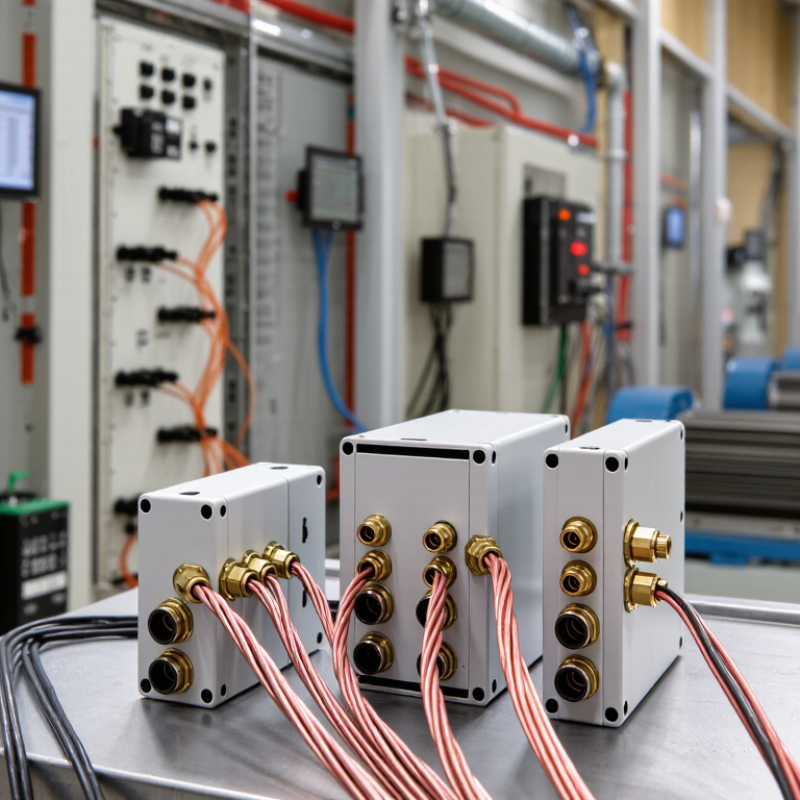
China Top Three Phase WYE EMI Filters Manufacturer
Three-phase WYE EMI filters control unwanted electrical noise in industrial power systems. Each phase connects through a filtering branch to a shared neutral point. Capacitors then provide a controlled path for high-frequency common-mode noise. Inductors resist rapid current changes and reduce differential-mode interference. The result is cleaner power for drives, controllers, sensors, and communication equipment.
The International Energy Agency reports that electric motor systems consume roughly 45% of global electricity. This makes effective interference control increasingly important in factories. MarketsandMarkets’ 2024 EMI Shielding Market report projects growth from about USD 7.6 billion in 2024 to USD 10.4 billion by 2029. The figures suggest stronger demand for practical EMC solutions. However, a filter is not magic. Its insertion loss depends on frequency, source impedance, load impedance, and installation length.
In field testing, engineers should check conducted emissions under realistic cable routing and load conditions. IEC 61800-3 provides useful EMC requirements for adjustable-speed drive systems. A WYE filter can support compliance by reducing noise before it reaches supply lines. Incorrect grounding can weaken performance. Long unshielded wires can also bypass the filter. This is where many designs fail. Careful terminal layout, low-impedance bonding, and repeatable testing remain essential. Even a well-rated component may underperform when the cabinet layout is careless.
| Technical Dimension | Reference Data or Definition | Core Function or Engineering Significance |
|---|---|---|
| Topology | Three-phase WYE, also called star-connected, using three line conductors and normally a neutral reference point. | Provides a defined structure for suppressing both line-to-line and line-to-ground electromagnetic interference in three-phase equipment. |
| Typical System Arrangement | Three phase lines, protective earth, and either a neutral conductor or an internal star point, depending on the filter design. | Allows the filter to address common-mode noise while maintaining compatibility with grounded industrial power systems. |
| Common Supply Ratings | Common low-voltage examples include 230/400 V AC at 50 Hz and 277/480 V AC at 60 Hz. The actual rating must match the installation. | Ensures that insulation, capacitors, clearances, creepage distances, and thermal design are suitable for the applied voltage and frequency. |
| Rated Current | Selected according to the continuous RMS current of the protected load, with consideration for overload, inrush, ambient temperature, and derating. | Prevents excessive temperature rise and avoids unwanted voltage drop during normal and transient operating conditions. |
| Differential-Mode Noise | Noise occurring between phase conductors, or between a phase conductor and neutral, and commonly associated with switching currents. | Series inductors and line-to-line capacitors attenuate high-frequency noise traveling between conductors. |
| Common-Mode Noise | Noise appearing in the same direction on multiple conductors relative to protective earth or chassis. | A common-mode choke and line-to-earth capacitors provide a high-frequency bypass path while limiting conducted emissions. |
| Main Filter Components | Common-mode choke, differential-mode inductance, X capacitors between conductors, Y capacitors from conductors to earth, discharge resistors, and protective components where required. | Creates frequency-dependent impedance that passes power-frequency energy while attenuating unwanted high-frequency components. |
| Operating Frequency | Designed for the rated power frequency, commonly 50 Hz or 60 Hz, while targeting interference typically occurring from the kilohertz range into the megahertz range. | Maintains low impedance at the power frequency and high attenuation over the relevant conducted-noise spectrum. |
| Insertion Loss | Specified in decibels and measured under defined source, load, impedance, frequency, and connection conditions; it is not a single universal value. | Quantifies the reduction of conducted interference. Higher dB values indicate greater attenuation under the stated test conditions. |
| Leakage Current | Current flowing through line-to-earth capacitors at the operating voltage and frequency; its value depends on capacitance, voltage, frequency, and system configuration. | Must be evaluated for protective-device compatibility, touch-current limits, and installations using residual-current protection. |
| Voltage Drop | The filter introduces impedance in the power path; the allowable drop depends on its inductance, resistance, load current, and operating frequency. | A low voltage drop helps preserve the input voltage available to motors, drives, power supplies, and other three-phase loads. |
| Application Areas | Variable-frequency drives, industrial automation systems, machine tools, renewable-energy converters, UPS systems, robotics, medical equipment, and switching power installations. | Reduces conducted emissions from power-electronic switching and helps protect sensitive equipment from incoming high-frequency disturbances. |
| Installation Position | Usually installed at the input or output boundary of the equipment enclosure, with short, low-inductance connections and a properly bonded protective-earth path. | Correct placement and wiring reduce parasitic coupling and help the filter achieve its specified attenuation. |
| Safety and Compliance References | Design and evaluation commonly consider the IEC 60939 series for passive filter units, applicable equipment safety requirements, and relevant conducted-emission limits such as CISPR standards. | Supports consistent evaluation of insulation, temperature rise, leakage current, dielectric strength, emissions, and mechanical safety. |
| Selection Criteria | System voltage, rated current, frequency, neutral configuration, grounding arrangement, required attenuation, leakage-current limit, enclosure environment, and available space. | Ensures that the selected three-phase WYE EMI filter performs effectively without creating overheating, resonance, nuisance tripping, or insulation problems. |
| Primary Benefits | Conducted-emission reduction, improved electromagnetic compatibility, lower interference coupling, and better system immunity when correctly integrated. | Helps equipment meet applicable EMC requirements and improves the reliability of systems operating near sensitive electronics. |
Check rated voltage, continuous current, leakage current, temperature range, and insertion-loss curves. Confirm values at your actual frequency and load. A 60 dB result at 1 MHz may differ at 150 kHz. Small details matter.
Filter performance changes across the frequency range. Request test curves covering your equipment’s real switching frequencies. One impressive test point is not enough. Numbers can mislead.
Request insulation resistance, dielectric-strength, capacitance, inductance, leakage-current, and temperature-rise results. Ask whether testing covers every unit or only selected samples. Sampling may reduce costs, but it can hide inconsistent units.
Review winding control, terminal torque, enclosure sealing, insulation handling, and batch traceability. Request samples from normal production. Specially selected samples may look perfect. Volume consistency matters more.
Ask for test reports, calibration records, material traceability, acceptance limits, and corrective-action records. Lot numbers should appear on products and records. Clear paperwork makes later investigation faster.
They are used in variable-frequency drives, UPS systems, HVAC equipment, charging systems, and automation cabinets. Their star-connected capacitors redirect common-mode noise toward protective earth. They can also reduce interference near sensors and communication lines.
Compare the filter’s leakage current with the equipment’s residual-current protection. Check the full system, not only the filter. This step is often overlooked. A suitable filter can still cause nuisance protection trips.
It can, but price alone proves little. Low-cost samples may contain undersized inductors or inconsistent capacitors. Verify components, test curves, thermal results, and batch records. No process is flawless. Honest review remains necessary.
Three Phase WYE EMI Filters are essential components for reducing electromagnetic interference in three-phase electrical systems. This article explains their definition, core functions, and WYE-connected structure, in which capacitors and filtering elements help direct common-mode and differential-mode noise away from sensitive equipment. By improving signal integrity and power stability, these filters support safer, more reliable operation in industrial and commercial applications.
It also outlines the key specifications for selecting a qualified Chinese manufacturer, including voltage and current ratings, insertion loss, leakage current, temperature range, mechanical design, and customization capabilities. Manufacturing standards, electrical safety requirements, routine testing, and quality-control procedures are discussed to show how consistent performance can be achieved. China-made Three Phase WYE EMI Filters offer practical advantages such as flexible design, competitive production efficiency, dependable noise suppression, and suitability for automation systems, power supplies, renewable-energy equipment, medical devices, and other demanding electrical installations.

