60+ Years of Power Engineering  ·  ISO 9001:2015 & ISO 13485 Certified Manufacturing
0%

Robotic Surgical Systems Power Supplies deserve attention before a robot enters the operating room. They feed imaging, control electronics, motors, and safety-critical sensors. A brief voltage dip can interrupt a procedure or trigger a system fault. The supply must fit the real load, not just the catalog’s headline wattage. Engineers should assess isolation, leakage current, electromagnetic compatibility, transient response, cooling, and backup behavior. IEC 60601-1 provides a central safety framework for medical electrical equipment. Compliance alone, however, does not prove that a power supply suits a particular robotic platform.

The market is expanding. Intuitive Surgical’s 2024 annual report recorded 9,902 da Vinci systems installed worldwide at year-end, with procedure volume up 17% from 2023. That growth makes dependable power design more than a component-selection detail. Robotics pioneer Russell H. Taylor’s human-centered research suggests a practical principle: engineering should support the clinical team’s work, not distract from it. This is a paraphrase, not a verbatim quotation. Buyers should compare verified test data, derating curves, fault protections, service life, and supplier traceability. Look closely at the thermal details. A compact enclosure beside warm motor drivers can expose weak cooling assumptions. No checklist is perfect; operating conditions vary, and vendor claims still need validation. The right choice balances safety, uptime, integration, and maintainability—not peak output alone.
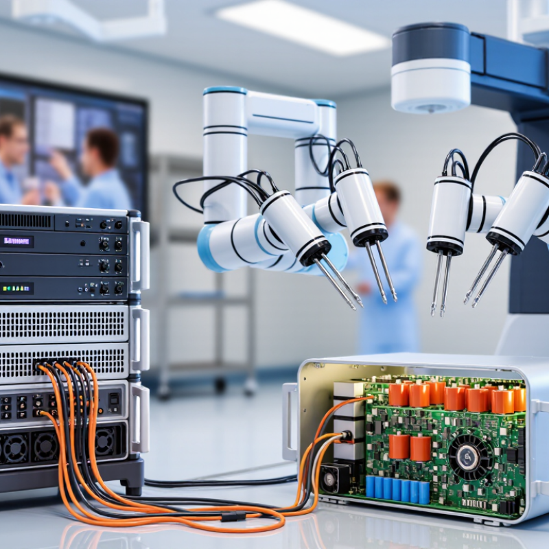
How to Choose Power Supplies for Robotic Surgical Systems

Define the Power Requirements of the Robotic Surgical System

Define the electrical envelope before selecting a power supply. List every load: arm-drive motors, vision cameras, processors, displays, and any integrated energy-delivery modules. Record each unit’s voltage, frequency, continuous draw, startup surge, and peak demand. Then model which loads operate together during a procedure. A motor braking or accelerating can create brief demand spikes that average-power estimates miss.

Measure real loads. Bench testing under representative motion helps reveal these peaks. Add headroom for startup and future modules, but avoid oversizing without reason; lightly loaded supplies may operate less efficiently. IEC 60601-1 provides a useful safety benchmark: its touch-current limits include 100 μA under normal conditions and 500 μA under a single-fault condition. Patient leakage limits vary by applied-part classification, so the system’s design determines which limits apply. Check the standard’s applicable requirements rather than treating these figures as universal.

Also define input-voltage variation, expected hold-up time, isolation needs, and the clinical environment. A brief mains interruption may reset a controller or interrupt an arm’s motion, so specify whether backup power must sustain the whole system or only safe shutdown. Verify performance with simultaneous motor movement, image processing, and display operation. The first load profile is rarely perfect. Revisit it after integration testing.

Identify Electrical Loads and Operating States

Before selecting a supply, map every electrical load to its operating state. A robotic surgical system may draw power for the surgeon’s console, imaging chain, motion controllers, brakes, and cooling fans. Record each load during startup, standby, active movement, and recovery after a brief interruption. Peak demand may occur when several servo axes accelerate together, not during steady cutting. Idle is not off.

Measure, don’t guess. Log input current while moving the arm through representative procedures, then capture short transients with suitable test equipment. Include accessories and battery charging; a monitor or instrument cart can change the total. IEC 60601-1:2005+A1:2012+A2:2020 sets patient leakage-current limits for Type CF applied parts of 10 µA in normal condition and 50 µA under a single fault. These are safety limits, not a power-supply sizing allowance. Check the applicable classification and system configuration.

Build a load table with watts, startup surge, duty cycle, and required hold-up time for each state. Test realistic transitions, such as standby to arm motion while imaging remains active. IEC 60601-1-2 addresses electromagnetic disturbances, so supply choice should also be checked within the finished system’s immunity testing. A paper estimate can miss a sharp transient. That happens. Leave documented margin, but revisit it when motors, cables, or software change; the “worst case” is easy to define too narrowly.

How to Choose Power Supplies for Robotic Surgical Systems - Identify Electrical Loads and Operating States

The figures below are representative planning estimates for a generic system, not product specifications. Actual loads vary by configuration, jurisdiction, and procedure. Confirm input ratings, startup current, and allowable voltage ranges with the equipment documentation before selecting a power supply.

Electrical Load Typical Operating State Estimated Input Power When Load Is Highest Power-Supply Sizing Considerations
Surgeon console computing and controls Low load in standby; sustained load when powered and controlling the system Approximately 100–300 W during operation System startup, application loading, or sustained processing Allow for continuous operation and startup demand. Include connected control electronics in the total load.
Patient-side cart control electronics Standby, ready, and active procedure states Approximately 100–400 W, depending on configuration When multiple control modules and communications interfaces are active Check whether the cart uses one input supply or several separately rated inputs; do not assume all modules share a power budget.
Manipulator and joint motor drives Low or near-zero motor demand while idle; variable demand during movement Approximately 200–800 W during motion; brief peaks may be higher Simultaneous arm movement, acceleration, or motion against mechanical load Check short-duration peak current, drive protection, and voltage droop. Size for the specified transient profile, not only average power.
Brakes and position-holding circuits Brakes change state during setup, positioning, or shutdown; holding circuits may remain energized Approximately 10–100 W, system-dependent Brake release or simultaneous state changes across several axes Verify whether brakes are energized to release or energized to hold, and account for their transition current and required safe state.
Vision processing and camera electronics Ready and active states; commonly continuous during a procedure Approximately 100–300 W Full camera, image-processing, and recording functions operating together Treat as a sustained load when active. Confirm whether image-processing equipment is powered from the robotic system or a separate supply.
Displays and operator interface screens Standby, ready, and active display states Approximately 50–250 W per display, depending on size and technology Multiple displays operating at normal brightness Count each display and its connected interface equipment. Include any startup current specified for the display power supply.
Endoscopic light source Off or low load in standby; increased load when illumination is enabled Approximately 50–250 W during use High illumination settings or light-source startup Confirm whether the light source is integrated or separately powered, and account for any associated cooling load.
Cooling fans and thermal management Variable operation based on temperature and system activity Approximately 20–150 W High ambient temperature, sustained processing, or elevated drive activity Include continuous cooling demand in the worst-case operating-state estimate; check for fan startup current.
Separate electrosurgical or energy-delivery equipment Low idle demand; substantially higher demand during energy delivery Highly equipment-dependent; output ratings can range from hundreds of watts to kilowatts Energy delivery, subject to the equipment’s rated output and operating mode Do not combine this load with the robotic-system estimate unless the equipment is explicitly powered by the same supply. Use its own input rating and applicable safety requirements.
System-level standby and auxiliary circuits Standby, charging, network-connected, or ready state Approximately 10–100 W, configuration-dependent Battery charging or multiple auxiliary modules active Measure or verify standby consumption and charging demand; these loads may remain present between procedures.

Selection workflow: List every connected load; record its input voltage, frequency, continuous rating, and startup or transient current; then calculate separate totals for standby, ready, active, and startup states. Check which loads can operate simultaneously, apply the required design margin, and verify medical electrical safety, grounding, isolation, and backup-power requirements against the applicable equipment documentation and standards.

Assess Patient Safety, Isolation, and Regulatory Needs

How to Choose Power Supplies for Robotic Surgical Systems

Assess Patient Safety, Isolation, and Regulatory Needs

A power supply in a surgical robot must do more than deliver stable voltage. It must keep hazardous energy away from patients and clinical staff, even during a fault. The World Health Organization’s 2024 Global Patient Safety Report estimates that one in ten patients experiences harm in healthcare, and unsafe care contributes to over three million deaths annually in low- and middle-income countries. These figures are not specific to power supplies, but they show why small electrical risks deserve serious attention. Small margins matter.

Start by identifying each patient connection and its required applied-part classification. IEC 60601-1 sets safety requirements for medical electrical equipment, including leakage current and protection against electric shock. Ask suppliers for test evidence covering normal operation and single-fault conditions, not just a datasheet summary. Check isolation barriers, creepage and clearance distances, and behavior when a motor drive stalls or a cable is damaged. A quiet bench test may miss the brief voltage dip that resets a surgical controller. ISO 14971 provides a risk-management framework for evaluating such hazards across the device lifecycle. Map the power architecture to the applicable market’s regulatory requirements early; a compliant component alone does not make the finished system compliant. And isolation is not a checkbox.

How to Choose Power Supplies for Robotic Surgical Systems — Assess Patient Safety, Isolation, and Regulatory Needs

Publication year is shown for the cited editions; it does not indicate which edition is currently adopted in a specific market. When selecting a supply, assess patient protection, isolation, leakage current, electromagnetic compatibility, and risk controls against the standards and regulatory requirements applicable to the finished system.

Compare Power Supply Options and Integration Constraints

Choosing a power supply for a robotic surgical system means balancing electrical performance with tight integration limits. An internal AC-DC unit can simplify cabling, but it adds heat inside the enclosure. An external supply may ease servicing, yet its cable and connector need secure routing. Modular supplies offer flexible outputs, though extra modules can increase size and complexity.

Compare options under real operating conditions. A motor arm may draw a sharp current spike while cameras and control boards need stable, low-noise power. Check peak loads, isolation, ripple, efficiency, cooling, and fault behavior. Then confirm that dimensions, mounting points, connectors, and service access fit the system. Verify applicable medical electrical safety and electromagnetic compatibility requirements with qualified engineers. A tidy spreadsheet can still miss a cable bend or a hot spot near a sensor. I would leave room for testing; early estimates are often optimistic.

Tips: Measure temperatures during motion tests, not just at idle. Keep power and signal cables sensibly separated. Document connector pinouts and service clearances. Compare total integration effort, not only purchase cost. One detail is easy to overlook.

Validate Performance Through Testing and Monitoring

A surgical system’s power supply should be tested under realistic operating conditions, not only on a quiet bench. Apply changing loads that reflect motors, imaging equipment, and control electronics starting or operating together. Measure voltage stability, ripple, startup behavior, and recovery after a sudden load change. Repeat tests at different temperatures and input conditions. Small details matter. A connector that feels secure during inspection may loosen after repeated movement.

Testing should also examine electrical noise and heat around the supply, cables, and nearby components. Record measurements and test conditions so engineers can compare results after design changes or maintenance. During operation, monitor output voltage, current, temperature, and fault events, using limits that trigger clear alerts before performance drifts too far. Keep the data. A test plan can still miss an unusual combination of loads; that is a useful gap to acknowledge, not conceal. Review monitoring trends regularly, since gradual temperature increases or brief voltage dips may point to a developing problem. Avoid relying on a single pass result. A result is only as useful as the conditions behind it.

FAQS

Which loads should be included in the power estimate?

List arm motors, cameras, processors, displays, and integrated energy modules. Record each load’s voltage, frequency, continuous draw, startup surge, and peak demand.

Why measure power during movement?

Motors can draw brief spikes while accelerating or braking. Test representative motion with imaging and displays running. Average figures can miss these peaks.

How much extra capacity should the supply provide?

Allow headroom for startup surges and planned modules. Avoid unnecessary oversizing, which can reduce efficiency at light loads. Estimates may need revision.

What electrical safety details need checking?

Check isolation and applicable touch-current requirements. IEC 60601-1 gives benchmark limits of 100 μA normally and 500 μA under a single fault. Patient leakage limits depend on applied-part classification.

Should the system use an internal or external power supply?

An internal unit can simplify cabling but adds enclosure heat. An external unit may ease servicing, though its cable and connector need secure routing.

What should be compared beyond output power?

Compare ripple, efficiency, cooling, fault behavior, mounting, connectors, and service access. Check dimensions carefully. A cable bend can disrupt a neat layout.

How should brief power interruptions be handled?

Define the required hold-up time and input-voltage range. Decide whether backup power must sustain the whole system or only support safe shutdown.

What should integration testing include?

Run motors, cameras, processors, and displays together. Measure temperatures during motion, separate power and signal cables sensibly, and document pinouts and service clearances. We may still miss a hot spot.

Conclusion

Choosing power supplies for robotic surgical systems begins with a clear picture of the equipment’s electrical demands. Identify every load, including motors, sensors, control units, displays, and communication components, and consider how consumption changes during startup, routine operation, standby, and peak activity. This helps define suitable voltage, current, power capacity, and transient-response requirements while allowing for appropriate operating margins.

Robotic Surgical Systems Power Supplies must also support patient safety through suitable isolation, dependable fault protection, and low-noise operation. Compare available supply options against the system’s space, cooling, cabling, and integration constraints, as well as its applicable regulatory requirements. Finally, verify performance under representative operating conditions. Testing should assess output stability, temperature, electrical noise, and behavior during load changes or faults; ongoing monitoring can help identify degradation and support reliable operation over the system’s service life.


Amelia

Amelia

Amelia is a dedicated marketing professional with a strong understanding of the company’s products, customers, and industry landscape. With a thoughtful, research-driven approach, she transforms complex product information into clear, practical, and engaging content that helps readers make informed......