Magnetic resonance imaging depends on a quiet electromagnetic environment. Even small interference can create lines, bands, or confusing shadows across diagnostic images. MRI Shielded Facility EMI Filters help control this problem by stopping unwanted radio-frequency energy from entering through power, control, communication, and service lines.
These filters are installed at shield penetration points, often beside copper or aluminum panels. Their metal housings must connect firmly to the room’s shielding system. A loose bond can become a hidden leakage path. The filter may look like a simple box, but its performance depends on grounding, cable routing, current rating, and frequency response. It must also tolerate the MRI room’s electrical load without overheating or creating unsafe voltage conditions.
Dr. Emanuel Kanal, a recognized MRI safety authority, has stated, “MRI is not a risk-free procedure.” His warning applies beyond the scanner itself. A shielded room, filter network, equipment cabinet, and installation team must work as one controlled system. Engineers usually verify insertion loss, continuity, insulation, and shielding effectiveness during commissioning. They should repeat those checks after renovations or equipment changes. Real facilities are rarely perfect. Door hardware shifts, cables are added, and maintenance work can weaken assumptions. That is why selecting MRI Shielded Facility EMI Filters requires more than comparing catalog specifications. It requires site measurements, documented testing, qualified installation, and practical review of future service needs. Small details matter. Sometimes, they decide whether an image is clinically useful or technically misleading.
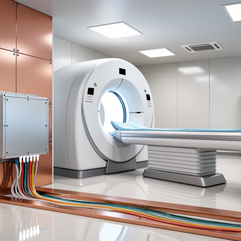
An EMI filter in an MRI shielded facility controls unwanted electrical noise entering or leaving the scan room. It is installed at power, lighting, communication, and service penetrations. The filter blocks radio-frequency interference while allowing normal power to reach approved equipment. This matters because MRI receivers detect extremely weak signals. A small switching-noise source can appear as lines, bands, or repeated patterns on images.
The filter must match the facility’s shielding design, voltage, current, and grounding method. IEC 60601-1-2:2020 defines electromagnetic compatibility test conditions for medical electrical equipment. ASTM F2503-20 also addresses equipment safety in the MR environment. These standards do not make every filter suitable. Test data should show insertion loss across relevant frequencies, including the MRI system’s operating range. A useful specification may show 80–100 dB attenuation, but only under stated test conditions. Installation quality remains critical. One loose bonding point can weaken an otherwise excellent shield. That is easy to overlook.
Tips: Request certified attenuation curves, not only a headline rating. Check leakage current, thermal capacity, and fault protection. Keep filter connections short and properly bonded. Ask for post-installation EMI testing inside the room. Experience shows that cable routing often causes more trouble than the filter itself. Recheck assumptions. Noise can come from nearby drives, lighting controls, or building services, and the first suspected source is not always correct.
What Is an MRI Shielded Facility EMI Filter?
Why MRI Facilities Require Specialized EMI Filtering
MRI systems operate with powerful magnetic fields, radiofrequency signals, and rapidly switching gradient equipment. These systems can detect extremely weak signals from the human body. Even minor electrical noise may distort images or interrupt an examination.
An EMI filter is installed where power, control, or communication lines enter the shielded room. It reduces unwanted high-frequency energy traveling through those pathways. The filter must match the circuit’s voltage, current, frequency range, and grounding design. A general industrial filter may look suitable, but it can perform poorly in an MRI environment.
The shielding enclosure also depends on careful installation. Gaps, poor bonding, or incorrectly routed cables can weaken the room’s protection. During site reviews, technicians often inspect filters alongside doors, panels, penetrations, and grounding connections. Testing should occur before clinical operation and after major electrical changes. A filter is not a magic fix. Interference may come from lighting, nearby equipment, or damaged shielding.
Practical experience shows that documentation matters. Installation records should identify each filter, its circuit, test results, and maintenance history. Small oversights can become expensive. Engineers should also coordinate with MRI specialists, electricians, and facility managers before selecting components. The right design protects image quality while supporting safe, reliable operation.
What Is an MRI Shielded Facility EMI Filter?
How EMI Filters Protect MRI Signal Quality and Safety
An MRI shielded facility EMI filter controls unwanted electrical noise entering or leaving the scan room. It is installed where power, alarms, lighting, or communication lines cross the RF shield. These entry points can behave like tiny antennas. Even weak interference may appear as lines, ripples, or repeating patterns across an MRI image.
A properly selected filter blocks high-frequency noise while allowing essential power and signals to pass. This helps protect the faint radiofrequency responses measured during scanning. Cleaner signals can support more reliable image interpretation. Filters also reduce interference with monitoring systems, emergency communication, and equipment controls. Patient safety depends on these systems working clearly, especially when staff must respond quickly.
Good design requires more than installing a filter and closing the panel. Engineers should review voltage, current, frequency range, grounding, cable routing, and the MRI system’s operating field. Nonmagnetic construction may be necessary near the scanner. Testing should include insertion loss measurements, shield continuity checks, and image-quality verification under realistic operating conditions. A filter is not magic. Poor bonding or an overlooked cable can defeat an otherwise strong installation. That is where experience matters. Small mistakes happen, and they deserve honest review before clinical use.
| Data Dimension | Representative Data | Why It Matters in an MRI Facility | Verification or Design Note |
|---|---|---|---|
| Primary function | Low-pass filtering of conducted electromagnetic interference on power, control, and signal penetrations | Reduces unwanted RF energy entering or leaving the shielded MRI room through cables and services | The filter should be installed at the shield boundary to prevent cable sections inside the room from acting as antennas |
| Typical filter type | Feed-through capacitor, multi-stage LC filter, or combined power-line EMI filter | The filter topology determines insertion loss, current capacity, transient behavior, and compatibility with connected equipment | Select the topology according to voltage, current, frequency range, grounding method, and medical-equipment requirements |
| MRI operating field strength | Common clinical systems include 1.5 T and 3 T; higher-field research systems may operate at 7 T or above | The static field and RF operating conditions affect equipment compatibility and the required shielding strategy | All components must be evaluated for static magnetic-field attraction, RF heating, vibration, and image compatibility |
| Approximate proton Larmor frequency | 1.5 T: 63.9 MHz; 3 T: 127.7 MHz; 7 T: 298.1 MHz | Interference near the MRI receive frequency can reduce signal-to-noise ratio and create artifacts | The filter and shield performance should be assessed across the receive band and other sensitive RF ranges |
| Common conducted-interference range | Often evaluated from approximately 150 kHz to 30 MHz for conducted emissions, with higher-frequency behavior also reviewed where applicable | Switch-mode power supplies, digital electronics, lighting controls, and building services can inject RF noise onto cables | The actual test range should follow the applicable EMC standard and the MRI system's site-acceptance requirements |
| Insertion loss | Specified in decibels as a function of frequency; no single value applies to every installation | Higher insertion loss at the relevant interference frequencies generally provides stronger attenuation of conducted RF noise | Use measured attenuation curves rather than a single headline value; installation, grounding, and load impedance affect performance |
| Power-line rating | Must match the circuit voltage, frequency, continuous current, inrush current, short-circuit rating, and number of phases | An undersized filter can overheat, nuisance-trip, saturate, or create an unsafe failure condition | Confirm ratings at the intended ambient temperature and include protective coordination with the upstream electrical system |
| Grounding and bonding | Filter cases and shield penetrations require low-impedance bonding to the RF shield and the facility grounding system as designed | Poor bonding can allow RF bypass paths that defeat the filter and increase leakage or touch-voltage risks | Avoid long grounding pigtails; use the installation method specified by the shield and electrical design |
| Signal and data penetrations | Copper lines may require filtered feed-throughs, while fiber-optic links provide galvanic isolation when suitable | Unfiltered copper conductors can conduct RF energy across the shield boundary | Cable shields, connector shells, and penetration panels must maintain continuous RF shielding |
| Medical electrical safety | Insulation, dielectric withstand, protective-earth continuity, leakage current, and temperature rise must be assessed | An EMI filter must not introduce an unacceptable shock, fire, or equipment-protection hazard | Apply the electrical and medical standards required by the jurisdiction and project specification |
| MRI safety compatibility | Non-ferromagnetic construction and controlled RF behavior are generally required inside or near the scanner environment | Ferromagnetic parts can become projectiles, while conductive structures may experience RF heating or induced currents | MRI safety classification and testing must be confirmed for the exact location and field strength |
| Shielding effectiveness | Usually expressed in decibels and measured over a defined frequency range; performance varies with frequency and construction | A strong shield can be compromised by doors, windows, ventilation, waveguides, seams, or unfiltered penetrations | Acceptance testing should examine the complete room, not only the filter enclosure |
| Image-quality impact | Possible symptoms include periodic lines, zipper artifacts, shading, loss of signal-to-noise ratio, or scan interruptions | EMI can be mistaken for scanner faults or can degrade diagnostic image consistency | Compare background noise and representative image sequences before and after corrective work |
| Maintenance requirements | Periodic inspection of terminals, bonding, enclosure condition, thermal performance, and insulation is recommended | Loose connections, corrosion, aging capacitors, or damaged shield interfaces can reduce attenuation and safety margins | Record test results and re-test after electrical modifications, filter replacement, or shield-room changes |
Note: Representative values and frequency examples are provided for engineering context. Final filter ratings, attenuation targets, grounding methods, and acceptance criteria must be established by the MRI system, electrical, EMC, and facility-safety specifications.
What Is an MRI Shielded Facility EMI Filter?
An MRI EMI filter is a boundary device installed where power or signal wiring enters the shielded room. It suppresses unwanted radio-frequency energy without interrupting essential services. The filter must preserve the room’s shielding continuity, grounding strategy, and electrical safety. IEC 60601-1-2:2014+A1:2020 requires medical electrical equipment to demonstrate electromagnetic compatibility under defined immunity and emissions tests. Therefore, a filter should be selected from measured interference risks, not from the MRI field strength alone.
Key components include capacitors, inductive elements, feedthrough terminals, grounding hardware, and a conductive enclosure. Some assemblies also separate power, lighting, monitoring, and emergency circuits. Insertion loss, rated current, voltage, leakage current, and frequency range require verification. Check the test curve. A single dB value can hide poor performance at critical frequencies. The 2024 ACR Manual on MR Safety emphasizes controlled access, zoning, and documented facility procedures; filter locations should support that safety plan. Place filters at the penetration panel, keep cable paths short, and bond the enclosure directly to the shield. Avoid unnecessary cable loops.
Installation quality matters more than appearance. Inspect every seam, fastener, and cable entry for continuity. Verify torque values and protective-earth connections. Commissioning should include shielding continuity checks, electrical safety tests, and RF spectrum measurements under operating conditions. A quiet scan room is not proof of complete protection. Site conditions change, and one overlooked cable can weaken an otherwise careful installation.
Key components and installation points of MRI EMI filters
The chart shows the proton Larmor frequencies used by common MRI field strengths. These frequencies are calculated from the proton gyromagnetic ratio of approximately 42.58 MHz/T. MRI EMI filters must reduce conducted radio-frequency interference across the scanner operating band and its relevant harmonics without affecting essential power or signal circuits.
Typical installation points include the main power entry, lighting circuits, HVAC and other conductive services, data and communication lines, monitoring cables, and the shielded-room penetration panel. Filter housings should be bonded directly to the RF shield, installed with short low-inductance connections, and verified after installation through insertion-loss, continuity, grounding, and shielding-effectiveness testing.
An MRI shielded facility EMI filter controls unwanted electrical noise entering or leaving the scan room. Selection starts with the equipment schedule, not a catalogue. Check voltage, current, phase, connector type, and installation location. The filter must match the MRI system, lighting circuits, monitoring devices, and emergency power paths.
IEC 60601-1-2:2014+A1:2020 identifies 3 Vrms conducted RF immunity and 10 V/m radiated RF immunity for applicable test conditions. These figures help define a reasonable performance target. However, they do not replace project testing. Ask for insertion-loss curves across the actual interference range, rather than one impressive number. IEEE 299 also supports shielding-effectiveness testing in dB. A filter rated for 100 dB at one frequency may perform less effectively elsewhere. That detail is easy to miss.
Tips: Use certified installation drawings. Keep filtered and unfiltered cables physically separated. Bond the filter enclosure to the shielded room with a short, wide connection. Inspect terminals during every planned maintenance visit. Look for heat marks, loose hardware, corrosion, and damaged cable glands. Review grounding resistance and repeat EMI measurements after renovations. In practice, assumptions fail. A visually perfect filter can hide a poor bond or overloaded circuit. The 2024 ACR Manual on MR Safety stresses controlled access, equipment checks, and documented safety processes; EMI maintenance should follow the same discipline. Record test instruments, calibration dates, frequencies, and results. Retest after replacing power equipment, modifying penetrations, or changing room electronics.
It is a boundary device installed where power or signal cables enter the shielded room. It reduces unwanted radio-frequency energy. Essential services continue normally. The filter also supports shielding continuity, grounding, and electrical safety.
Install it at the room’s penetration panel. Keep cable paths short and avoid unnecessary loops. Bond the enclosure directly to the shield. Poor placement can weaken an otherwise careful installation.
Common components include capacitors, inductive elements, feedthrough terminals, and grounding hardware. A conductive enclosure surrounds these parts. Some systems separate power, lighting, monitoring, and emergency circuits.
Start with the equipment schedule, not a catalogue. Check voltage, current, phase, connector type, and installation location. Confirm compatibility with lighting, monitoring, and emergency power circuits. The strongest-looking option may not fit the actual circuit.
They show filter performance across different frequencies. One impressive decibel value can hide weak performance elsewhere. Request curves covering the expected interference range. That detail is easy to miss.
Inspect every seam, fastener, terminal, and cable entry. Verify torque values and protective-earth connections. Use a short, wide bond to the shield. Keep filtered and unfiltered cables physically separated. Small gaps matter.
Inspect terminals during scheduled maintenance visits. Look for heat marks, loose hardware, corrosion, and damaged cable glands. Review grounding resistance and repeat electromagnetic measurements. Record instruments, calibration dates, frequencies, and results.
Retest after replacing power equipment or modifying cable penetrations. Repeat testing after changing room electronics. Commissioning should include continuity, electrical safety, and RF spectrum checks. A quiet scan room does not prove complete protection. Assumptions sometimes fail.
An MRI shielded facility EMI filter is a specialized device designed to control unwanted electromagnetic interference entering or leaving an MRI examination room. MRI systems rely on extremely sensitive radiofrequency signals to produce clear images, so interference from power lines, communication equipment, lighting, and nearby electrical systems can reduce image quality and disrupt reliable operation. MRI Shielded Facility EMI Filters help preserve the electromagnetic integrity of the room while supporting the safety and performance requirements of the imaging system.
These filters typically work with the room’s shielding system and are installed at key points where electrical services pass through the shielded enclosure, including power, lighting, control, and auxiliary circuits. Proper selection should consider voltage, current capacity, frequency performance, grounding, compatibility, and the MRI facility’s operating environment. Correct installation, inspection, and routine maintenance are also essential to prevent leakage, connection problems, or performance degradation. A well-designed filtering system contributes to stable MRI operation, consistent signal quality, and long-term facility reliability.