60+ Years of Power Engineering  ·  ISO 9001:2015 & ISO 13485 Certified Manufacturing
0%

Choosing MIL COTS EMI Filters is rarely a simple catalog exercise. Engineers must balance attenuation, voltage rating, current capacity, insertion loss, temperature range, and mechanical fit. A filter that performs well in a laboratory may behave differently inside a crowded avionics enclosure. Cable length, grounding, connector construction, and switching frequency can change the result.

Henry W. Ott, a widely respected EMC engineer, said, “There are three ways to solve an EMC problem: change the design, change the design, or change the design.” His point remains practical. A filter cannot repair every weakness in a poorly controlled power path. It should support a complete electromagnetic compatibility strategy.

This guide presents ten practical tips for selecting MIL COTS EMI Filters. It considers real installation conditions, not only datasheet values. Look closely at impedance curves, leakage current, transient performance, derating, and qualification evidence. Ask whether the filter suits the actual platform, including vibration, humidity, shock, and limited maintenance access.

Small details matter. A metal enclosure seam can undermine careful filtering. A long return path can create an unexpected antenna. These mistakes are common.

There is also room for doubt. No single filter is ideal for every mission profile. Laboratory data may not predict the final system perfectly. Engineers should verify assumptions through conducted and radiated emissions testing, thermal checks, and mechanical inspection. The right choice is usually the one that performs consistently after installation, not merely the one with the most impressive specification.
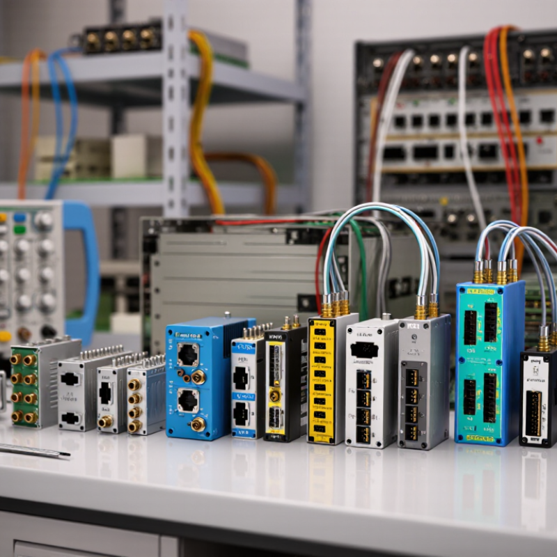
10 Tips for Choosing MIL COTS EMI Filters?

Defining MIL-COTS EMI Filter Requirements

Defining MIL-COTS EMI Filter Requirements

A MIL-COTS EMI filter should begin with the platform’s real electrical conditions, not a preferred catalog size. Record the maximum voltage, continuous current, startup surge, ripple, and allowable leakage current. Then identify the interference path. Is the problem conducted noise on power lines, signal coupling, or both?

Define the frequency range with measured evidence. A spectrum analyzer can reveal a sharp switching peak that a broad test specification may hide. Specify insertion loss at relevant frequencies, using the actual source and load impedance when possible. Common-mode and differential-mode performance should be listed separately. Do not rely on one impressive attenuation number.

Mechanical and environmental requirements are equally important. Check enclosure volume, connector type, mounting method, grounding path, temperature range, vibration, humidity, altitude, and shock exposure. The filter must survive the same conditions as the equipment. A perfect electrical part can fail through a weak chassis bond.

Small details matter.

I have seen teams select filters from nominal current alone. That approach looked efficient, but it ignored inrush and thermal rise. Define test methods, acceptance limits, and required documentation before procurement.

Include dielectric strength, insulation resistance, failure-mode behavior, and traceable inspection records. Requirements should also address maintainability and replacement access. Some assumptions will remain uncertain. Mark them for verification through testing, rather than hiding them in the specification.

Matching Filter Types to Power and Signal Lines

10 Tips for Choosing MIL COTS EMI Filters?
Matching Filter Types to Power and Signal Lines

Choosing a MIL COTS EMI filter starts with identifying the line type. Power lines carry energy, while signal lines carry meaning. They need different electrical behavior.

For DC power, check voltage rating, continuous current, pulse current, and insertion loss. A differential-mode filter can reduce noise between positive and return conductors. A common-mode filter targets noise traveling on both conductors together. Pi and feedthrough designs may provide stronger attenuation, but they can add capacitance and leakage current. Measure the source and load impedance before selecting one. Datasheet performance may change significantly in a real enclosure.

Signal lines require more restraint. A low-pass filter may protect a slow sensor line, but it can distort fast edges. High-speed links need controlled impedance, low parasitic capacitance, and bandwidth above the useful signal range. For twisted pairs, common-mode filtering often works better than heavily loading each conductor. Digital lines also need attention to rise time, not only clock frequency. A filter can pass the clock and still damage the data eye.

Keep the return path short. Bond the filter housing properly. Test with the actual cable, connector, and enclosure. I would not trust a bench result alone. My first filter choice is sometimes too aggressive, especially near converters. Recheck temperature rise, conducted emissions, and immunity after installation. Small layout changes can undo a good component selection.

MIL-COTS EMI Filter Selection: Representative Insertion Loss by Frequency

Power-line LC filters generally provide stronger low-frequency attenuation, while signal-line feedthrough filters are optimized to suppress higher-frequency interference while preserving signal integrity. The values below are representative engineering-level insertion-loss figures in dB; actual performance depends on impedance, source/load conditions, layout, current, and filter construction.

Selection guide: use a power-line LC filter for DC or power input/output paths, and use a signal-line feedthrough or filtered connector for data, control, and low-level analog lines where bandwidth and waveform integrity must be maintained.

Evaluating Electrical, Mechanical, and Environmental Ratings

10 Tips for Choosing MIL COTS EMI Filters

Choosing a MIL COTS EMI filter starts with electrical ratings, not appearance. Check the system voltage, continuous current, ripple current, and expected transients. A filter rated for 28 volts may still fail under a sharp load surge. Measure the noise. Review insertion loss across the actual interference band, not only the headline frequency. Leakage current and impedance also affect sensitive power converters.

Mechanical ratings deserve equal attention. Confirm the mounting pattern, terminal size, enclosure clearance, and connector alignment before ordering samples. A compact filter can create wiring stress inside a crowded chassis. Fit matters. Check vibration and shock data against the equipment profile, including resonance points. During one prototype build, a filter passed bench tests but loosened after repeated vibration. The mounting hardware needed improvement, not the circuit.

Environmental ratings reveal whether the filter can survive real service conditions. Examine operating and storage temperatures, humidity, altitude, salt fog, dust, and fluid exposure. Ask for test methods, duration, and documented results. “Qualified” is not always specific enough. Derating current at high temperature may prevent premature aging. Sealing can also change thermal performance. Do not guess. Inspect the test report and compare it with the installation location. I have sometimes trusted a familiar rating too quickly; field conditions were harsher than the laboratory assumptions. That remains an important design warning.

Verifying Military Standards and System Compatibility

10 Tips for Choosing MIL COTS EMI Filters

Verifying military standards is more than checking a certificate. Request the complete test report, revision number, and laboratory scope. A filter may meet one requirement while missing another. For example, MIL-STD-461 testing can address conducted emissions, susceptibility, or both. Confirm the exact test methods used. Then compare them with your platform’s compliance plan.

System compatibility deserves equal attention. Check the filter’s rated voltage, continuous current, pulse current, and operating temperature. Measure the available enclosure space, including cable bend radius. A compact filter is useless if its connector blocks a service panel. Review insertion-loss curves across your actual frequency range, not only the headline value. Also inspect source and load impedance. Laboratory results can change inside a real power network.

Grounding details often decide performance. Verify whether the filter needs a chassis bond, shield termination, or a dedicated return path. A long pigtail can weaken high-frequency attenuation. Confirm insulation resistance, dielectric strength, vibration limits, and humidity testing under the applicable military standard. Ask whether testing covered the installed configuration, including connectors and wiring. That point is easy to overlook.

Field experience teaches caution. We once treated a passing test as final proof, but the installed cable routing changed the noise result. The lesson was uncomfortable. Standards verification is necessary, not sufficient. Keep traceable records, test samples from the production lot, and challenge assumptions before approving the filter.

10 Tips for Choosing MIL COTS EMI Filters? - Verifying Military Standards and System Compatibility

No. Selection Tip What to Verify Relevant Standard or Test Area Compatibility Checks Practical Acceptance Criteria
1 Define the EMI problem first Identify whether the main issue is conducted emissions, conducted susceptibility, radiated emissions, or radiated susceptibility. MIL-STD-461 test families, such as CE101, CE102, CS101, CS114, RE102, and RS103, as applicable to the equipment category. Confirm that the filter is installed on the affected power or signal interface and that the interference path is understood. The selected filter addresses the measured frequency range and does not rely solely on a generic insertion-loss claim.
2 Check the required military qualification Review the exact specification number, revision, slash sheet, qualification status, and applicable test conditions. MIL-PRF-15733 may apply to certain radio-frequency interference filter and capacitor products; the contract or equipment specification remains controlling. Do not treat a commercial datasheet or “military grade” description as proof of compliance with a procurement specification. Obtain a current certificate of compliance, qualification report, or other traceable documentation required by the program.
3 Match voltage and current ratings Compare continuous voltage, transient voltage, DC or AC operation, RMS current, peak current, and inrush current. The filter data sheet and the platform power-interface requirements should be evaluated together. Check line-to-line and line-to-chassis voltage, polarity, phase arrangement, insulation rating, and creepage or clearance requirements. Ratings include suitable margin for normal operation, foreseeable transients, temperature, and startup conditions.
4 Evaluate insertion loss correctly Review insertion-loss curves together with the stated source and load impedance, test fixture, frequency range, and termination method. Insertion loss is a test-dependent parameter and should be related to the applicable conducted-emissions or susceptibility requirement. Compare the filter’s measured performance with the actual system impedance and cable configuration. The filter provides adequate attenuation at the frequencies requiring control under representative installation conditions.
5 Confirm grounding and bonding provisions Examine case construction, chassis termination, mounting hardware, shield termination, and earth or return-current paths. MIL-STD-461 installation practices and the platform grounding and bonding design should be considered during integration. Use a low-impedance, short connection to the intended chassis reference; avoid long pigtails that can add inductance. The installed filter maintains the intended high-frequency return path without creating unsafe or unintended ground-current paths.
6 Check environmental durability Review operating and storage temperature, humidity, vibration, shock, altitude, corrosion, sealing, and fluid exposure. MIL-STD-810 test methods may be specified for environmental qualification, but the applicable methods and severities depend on the platform. Confirm the filter enclosure, terminals, potting, mounting, and derating remain suitable for the installation environment. Environmental limits and test severities match the equipment-level environmental requirements rather than being assumed from the military application alone.
7 Assess leakage current and safety Determine capacitive leakage, discharge behavior, dielectric withstand, insulation resistance, and possible residual stored energy. Apply the equipment safety requirements, power-system rules, and relevant filter safety tests specified by the program. Check whether leakage affects protective devices, ground-fault monitoring, isolation requirements, or maintenance procedures. Leakage and discharge values remain within system limits, and required safety warnings or discharge components are included.
8 Control resonance and power interaction Review filter impedance, damping, capacitor values, converter control bandwidth, and possible negative-input-impedance interaction. Power-interface verification should include conducted-susceptibility and transient requirements applicable to the equipment. Analyze the filter with the upstream source impedance and downstream converter or load across operating modes. No unacceptable oscillation, startup failure, control-loop instability, excessive ripple, or transient overshoot occurs.
9 Verify mechanical and interface fit Check package size, mass, mounting pattern, connector or terminal type, wire gauge, keying, orientation, and service access. The filter must conform to the equipment drawing, interface control document, and applicable connector or enclosure requirements. Confirm creepage, clearance, cable bend radius, thermal airflow, shielding continuity, and compatibility with the enclosure material. The filter can be installed without adapters or unapproved wiring changes and does not compromise sealing or structural integrity.
10 Validate the complete system Perform equipment-level testing after installation, including emissions, susceptibility, power transients, thermal behavior, and functional operation. MIL-STD-461 and other contractually specified platform standards should be tested using the final harness, grounding, enclosure, and operating modes. Test worst-case loads, cable lengths, switching states, external interfaces, and maintenance configurations that can alter EMI performance. The integrated equipment meets the required limits with documented test configuration, calibration records, deviations, and corrective actions.

Note: The applicable military standard, revision, test method, and acceptance limit should always be taken from the governing contract, equipment specification, and platform-level compliance plan.

Comparing Testing, Reliability, Cost, and Supplier Support

10 Tips for Choosing MIL COTS EMI Filters

Testing should mirror the platform, not a laboratory fantasy. Select filters tested under MIL-STD-461G limits, then review temperature, vibration, humidity, and shock results.

Tip 1: Request complete test reports.
Tip 2: Check test fixtures and cable lengths.
Tip 3: Confirm conducted and radiated emission data.

MIL-STD-202 methods reveal whether components survive mechanical and environmental stress. Small details matter. A missing fixture description can weaken an impressive graph.

Reliability deserves more than a predicted number. MIL-HDBK-217F remains widely referenced for failure-rate estimates, but field conditions can differ sharply.

Tip 4: Ask for failure-rate assumptions.
Tip 5: Compare derating rules.
Tip 6: Review lot history and corrective-action records.

The U.S. Government Accountability Office has repeatedly identified supplier concentration and limited supply-chain visibility as defense risks.

Tip 7: Prefer traceable materials and stable production sites.
Tip 8: Request lifecycle and obsolescence plans.

I would not accept “military grade” as evidence. It is only a starting phrase.

Cost comparisons should include installation and future support. A lower unit price may require extra shielding, retesting, or manual rework.

Tip 9: Calculate total ownership cost across qualification, inventory, and replacement.
Tip 10: Score supplier response time, engineering access, and documentation quality.

The 2023 U.S. Department of Defense Industrial Capabilities Report emphasizes resilient sourcing and production visibility.

That does not guarantee performance. Yet it supports a practical rule: suppliers should provide measurable evidence, not polished promises. Ask difficult questions. Then record the answers.

FAQS

Which electrical ratings should be checked before selecting an EMI filter?

Check system voltage, continuous current, ripple current, and expected transient surges. A 28-volt system can still damage a filter during a sharp load spike. Measure actual noise. Review insertion loss across the real interference range.

Why should insertion loss be reviewed across several frequencies?

A headline frequency may not match your system’s interference band. Compare the filter curve with measured noise from converters, motors, and cables. Also check leakage current and source-load impedance. One impressive number is not enough.

What mechanical details can cause installation problems?

Confirm mounting holes, terminal dimensions, enclosure clearance, and connector alignment. Check cable bend radius inside the chassis. A small filter may press against wiring or block a service panel. Fit matters.

How should vibration and shock performance be evaluated?

Compare tested vibration and shock levels with the equipment’s actual profile. Include resonance points and mounting hardware. A bench-tested filter may loosen after repeated vibration. The hardware, not the circuit, may fail.

Which environmental conditions should be included in the evaluation?

Review operating and storage temperatures, humidity, altitude, salt fog, dust, and fluid exposure. Request test methods, durations, and documented results. High temperatures may require current derating. Sealing can also reduce cooling.

Does passing a military standard prove system compatibility?

No. Confirm the exact test methods, revisions, fixtures, cable lengths, and laboratory scope. Check whether testing included the installed connectors and wiring. A passing test is necessary, not sufficient.

How do grounding and cable routing affect filter performance?

Verify chassis bonding, shield termination, and dedicated return paths. Keep high-frequency connections short. A long pigtail can weaken attenuation. Cable routing once changed our noise result, so assumptions deserve testing.

How should reliability, cost, and supplier support be compared?

Review failure-rate assumptions, derating rules, lot history, and corrective-action records. Check material traceability, production stability, and obsolescence planning. Calculate qualification, inventory, replacement, shielding, and rework costs. A cheaper unit may cost more later.

Conclusion

Selecting the right MIL COTS EMI Filters begins with clearly defining the system’s electromagnetic interference requirements, operating voltage, current, frequency range, and installation constraints. The filter type should match the application, whether it is intended for power input/output lines, sensitive signal circuits, or mixed electrical interfaces. Careful evaluation of insertion loss, impedance, voltage and current ratings, size, mounting method, thermal performance, vibration resistance, and environmental durability helps ensure dependable operation in demanding conditions.

A complete selection process should also verify applicable military standards, qualification procedures, grounding methods, and compatibility with the overall platform. Engineers should compare test data, reliability expectations, service life, availability, total cost, and supplier support rather than focusing only on initial price. Documentation, customization capability, technical assistance, and long-term supply stability can significantly affect project success. By balancing electrical performance, mechanical integration, environmental protection, compliance, and lifecycle value, users can choose filters that improve system resilience and reduce the risk of interference-related failures.


Evelyn

Evelyn

Evelyn is a dedicated marketing professional with a deep understanding of the company’s products, customers, and market dynamics. Through thoughtful research and clear communication, she transforms complex product information into practical insights that help readers make confident decisions. As a......