Explore our high-performance power supply platforms, SMPS units, and customized PCBA assemblies incorporating enterprise-grade flyback transformer architectures.
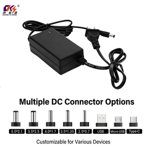
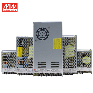
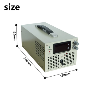
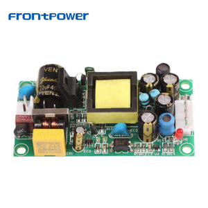
In modern switched-mode power supply (SMPS) design, the flyback transformer (technically a multi-winding coupled inductor) serves as the primary energy storage and galvanic isolation element. Unlike standard power transformers that transfer energy instantaneously from primary to secondary turns, a flyback transformer stores magnetic energy in its core during the primary switch turn-on cycle ($E = \frac{1}{2} L_p I_p^2$) and discharges that energy into the output circuit during the off-cycle.
Achieving CE Certification (Conformité Européenne) for flyback transformers requires rigorous adherence to European safety directives, including the Low Voltage Directive (LVD) 2014/35/EU, the Electromagnetic Compatibility (EMC) Directive 2014/30/EU, and the RoHS 3 Directive (EU) 2015/863. As a premier original equipment manufacturer (OEM), our facility engineers high-frequency transformer topologies that solve the core engineering dilemma: maximizing efficiency and power density while guaranteeing robust isolation barrier integrity under stringent thermal and electrical transient conditions.
The maximum power throughput capability of a flyback core is directly governed by core volume, saturation flux density ($B_{sat}$), and switching frequency ($f_{sw}$):
P_{out} = \frac{1}{2} \cdot L_p \cdot I_{peak}^2 \cdot f_{sw} \cdot \eta
Where $L_p$ is primary inductance, $I_{peak}$ is peak primary current, $f_{sw}$ is operational switching frequency, and $\eta$ is overall energy conversion efficiency.
Our custom planar and bobbin-wound flyback components support switching frequencies from 50 kHz up to 2.5 MHz, utilizing high-permeability MnZn and NiZn ferrite cores engineered to withstand severe thermal stress and continuous duty cycles.
Built on over six decades of custom magnetics design, our manufacturing infrastructure delivers certified reliability for critical industrial, medical, and defense applications.
Partnering directly with a certified flyback transformer factory eliminates supply chain friction, ensures strict insulation compliance, and lowers overall cost of ownership.
We source premium MnZn soft ferrite formulations featuring low core loss characteristics ($P_v \le 300 \text{ kW/m}^3$ at 100 kHz, 200 mT, 100°C). Available in EE, EFD, PQ, RM, ETD, and custom planar core shapes to fit ultra-compact 1U and desktop enclosures.
Full compliance with IEC/EN 62368-1 for IT/AV equipment and IEC/EN 60601-1 3rd Edition for medical systems. Utilizing Triple Insulated Wire (TIW), reinforced margin winding, and vacuum pressure impregnation (VPI) for Class B (130°C), Class F (155°C), and Class H (180°C) thermal systems.
Interleaved primary and secondary winding techniques dramatically reduce stray magnetic energy. Our precision automated winding controls leakage inductance down to less than 1.5% of total primary inductance, suppressing voltage spikes and reducing snubber circuit power dissipation.
Incorporating custom internal copper foil shielding (Faraday shield) between winding layers to minimize inter-winding capacitance ($C_{ps}$). This attenuates common-mode noise propagation across the isolation barrier, facilitating system-level compliance with CISPR 32 / FCC Class B limits.
Equipped with multi-axis CNC winding machinery, automated laser pin stripping, and fully automated vacuum varnish dipping stations. Eliminates human error, guarantees uniform turn placement, and ensures 100% partial discharge suppression.
Every single manufactured transformer undergoes rigorous automated parametric testing: primary turn ratio, inductance ($L_p$), leakage inductance ($L_{lk}$), DC resistance (DCR), hi-pot dielectric withstand (up to 5kV AC), and surge impulse testing prior to global export packaging.
Selecting the correct magnetic core architecture based on power throughput, creepage requirements, and thermal constraints.
| Core Geometry Type | Typical Power Range | Operating Freq. ($f_{sw}$) | Creepage / Clearance | Isolation Level | Target Application |
|---|---|---|---|---|---|
| EFD15 / EFD20 | 5W – 25W | 65 kHz – 300 kHz | > 5.0 mm | 3000V AC (Reinforced) | IoT Devices, Auxiliary Bias Supplies, Smart Meters |
| EE25 / EF25 | 20W – 60W | 50 kHz – 150 kHz | > 6.4 mm | 3750V AC (Basic/Reinforced) | Desktop Power Adapters, CCTV Systems, Industrial PCBA |
| PQ2620 / PQ3230 | 50W – 150W | 100 kHz – 500 kHz | > 8.0 mm | 4000V AC (2xMOPP Medical) | Medical Power Supplies, High-Power LED Drivers, Telecom |
| Planar EQ25 / ER28 | 40W – 200W | 250 kHz – 2.5 MHz | Multilayer PCB Clearance | 2500V AC – 4000V AC | Ultra-Thin Adapters, GaN-based SMPS, Aerospace & Defense |
| RM8 / RM10 | 30W – 100W | 80 kHz – 250 kHz | > 6.0 mm | 3000V AC (Reinforced) | High-Density Industrial Drives, Audio Equipment, SMPS |
As global regulatory bodies accelerate efficiency standards (such as EU EcoDesign Directive Tier 2 and US DoE Level VI), procurement teams face evolving architectural requirements when sourcing flyback transformers for high-volume SMPS manufacturing:
Looking toward the next decade of power conversion magnetics, three primary technological trends are reshaping flyback transformer manufacturing:
Replacing traditional wire-wound bobbins with multi-layer printed circuit board (PCB) traces. Planar transformers deliver unmatched thermal dissipation, ultra-low profile packaging (< 8mm height), and near-zero unit-to-unit parasitic variation.
While manganese-zinc ferrites dominate cost-sensitive applications, ultra-high permeability nanocrystalline magnetic cores are expanding into high-temperature, compact flyback topologies due to higher saturation flux density ($B_s = 1.2 \text{ T}$) compared to conventional ferrites ($B_s \approx 0.45 \text{ T}$).
Thermally conductive polyurethane and epoxy encapsulation compounds are replacing traditional varnish, enabling flyback components to operate in harsh industrial, marine, and explosive atmospheres (HazLoc / ATEX) with enhanced mechanical vibration damping.
In-depth technical responses covering safety certifications, structural design, thermal ratings, and OEM custom lead times.
Consult directly with our magnetics application engineers to review your circuit schematic, determine core topology, request sample prototypes, or obtain CE compliance documentation.
