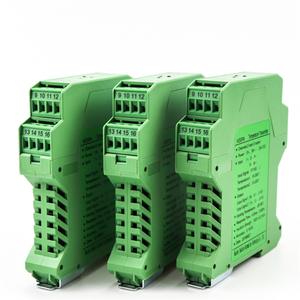
Explore our industrial-grade, CE-compliant signal measurement transmitters, split-core voltage/current sensors, and custom pulse transformers designed for high-reliability OEM integration.
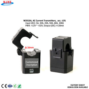
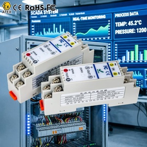
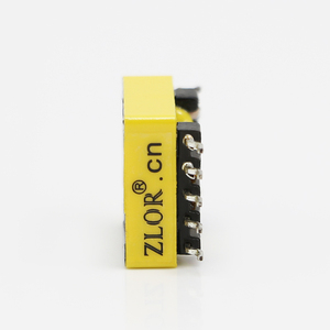
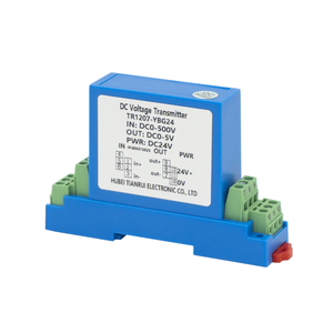
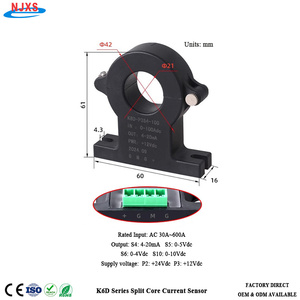
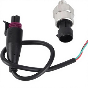
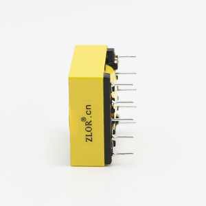
From medical-grade equipment to military-spec defense systems and high-density semiconductor fabs, our CE-certified transducers represent the apex of signal accuracy and ruggedized electrical isolation.
Our transducers deliver up to 5,000V AC RMS galvanic isolation between primary inputs, secondary outputs, and auxiliary supply rails. Engineered to eliminate ground loops and protect delicate PLCs and DAQ infrastructure.
Manufactured inside certified facilities implementing full lot traceability, automated optical inspection (AOI), and strict quality management systems tailored for high-reliability medical and defense applications.
Every individual voltage sensor undergoes multi-point linear calibration, automated temperature-compensated thermal burn-in, and dielectric withstand testing before global shipment.
A comprehensive engineering evaluation of high-voltage isolation, optical feedback sensing, linear Hall-effect measurement, and global CE compliance standards.
In modern industrial automation, renewable energy conversion, and medical diagnostic equipment, the requirement for real-time electrical monitoring has evolved from basic over-voltage protection into high-speed dynamic control telemetry. A voltage transducer (also known as a voltage transmitter or isolated signal converter) serves as the critical bridge between lethal, high-potential AC/DC power buses and low-voltage digital microcontrollers, Programmable Logic Controllers (PLCs), and Supervisory Control and Data Acquisition (SCADA) systems.
As a leading CE Certified Voltage Transducer Manufacturer & Factory, our global engineering operations prioritize three essential technical metrics: absolute linearity across wide operating temperatures, high dynamic bandwidth for harmonic spectrum analysis, and robust galvanic isolation capable of sustaining continuous common-mode voltage stress without dielectric breakdown.
Selecting the appropriate voltage transducer requires a deep structural understanding of sensing physics. Transducers generally fall into three main technological categories, each engineered for specific industrial trade-offs:
Optically coupled voltage transducers utilize a precision internal resistive voltage divider on the primary input, converting the proportional current signal into an optical pulse-width modulated (PWM) or analog infrared flux. A matched photodiode receiver on the secondary side reconstructs the original voltage amplitude.
Hall-effect transducers utilize a primary winding that generates a magnetic flux within a high-permeability toroidal core. A Hall sensor positioned in the core air gap detects this flux and drives a secondary compensation coil to create an opposing flux (zero-flux magnetic balance).
Utilizing step-down step-up precision potential transformers (PTs) coupled with active precision rectifiers or RMS-to-DC converters, these units convert pure sinusoidal AC grid voltages into industrial 4-20mA current loops or 0-10V DC signals.
To assist power design engineers and procurement teams in evaluating transducer topologies, the following benchmark table highlights key performance metrics:
| Transducer Topology | Linearity Error | Response Time | Galvanic Isolation | DC & AC Bandwidth | Thermal Drift Coefficient |
|---|---|---|---|---|---|
| Closed-Loop Hall Effect | < 0.1% FS | < 1.0 μs | 3.0 kV to 4.5 kV AC | DC to 150 kHz | ± 0.01% / °C |
| Optical Amplification | < 0.2% FS | < 3.0 μs | 5.0 kV AC RMS | DC to 500 kHz | ± 0.02% / °C |
| Modulated Fluxgate | < 0.05% FS | < 0.5 μs | 4.0 kV AC RMS | DC to 300 kHz | ± 0.005% / °C |
| Active Isolation PT | < 0.5% FS | < 50 ms (True RMS) | 2.5 kV AC RMS | 45 Hz to 400 Hz (AC Only) | ± 0.03% / °C |
The global market for electrical measurement transducers is undergoing a significant transformation driven by the transition toward Wide Bandgap (WBG) semiconductors (Silicon Carbide - SiC, and Gallium Nitride - GaN), decentralized smart grids, and stringent international safety mandates. Key trends shaping procurement decisions include:
Modern power converters operating at switching frequencies exceeding 100 kHz generate extreme fast voltage transients ($\text{d}V/\text{d}t > 50 \text{ kV}/\mu\text{s}$). Legacy transducers fail in these environments due to high parasitic capacitance, which allows common-mode noise to corrupt the secondary control loop. Next-generation transducers incorporate ultra-low parasitic capacitance ($< 5\text{ pF}$) shielded primary windings and differential output stages to ensure uncorrupted signal integrity.
While traditional 4-20mA current loops and 0-10V analog signals remain popular due to legacy PLC compatibility, global procurement is rapidly shifting toward integrated digital microcontrollers within the transducer enclosure. Smart transducers providing direct RS485 Modbus RTU, CANopen, or Ethernet/IP eliminate the need for external analog-to-digital converter (ADC) modules, reducing total system bill-of-materials (BOM) costs.
Factory automation and outdoor renewable installations demand uninterrupted performance under extreme environmental stress (-40°C to +85°C). Industrial buyers increasingly mandate automated temperature calibration protocols, ensuring that zero-offset drift and span gain errors are actively cancelled across the entire thermal operating envelope.
For industrial original equipment manufacturers (OEMs) exporting to the European Union and North America, purchasing transducers without accredited third-party certification introduces immense compliance risks. Our manufacturing operations strictly adhere to international directives:
Detailed engineering and supply chain answers from our technical application specialists.
Require specialized voltage sensing, custom signal conditioning, or high-volume factory pricing? Speak directly with our senior applications engineering team today.
Get a Quote